Methods of implanting wireless device within an anatomical cavity during a surgical procedure

a technology of anatomical cavity and wireless device, which is applied in the field of surgical procedure of implanting wireless device within an anatomical cavity, can solve the problems of rhc not being able to directly measure left side pressure and contractility, and the use of rhc posing several risks, and the effect of delivering an implant via catheterization

Inactive Publication Date: 2007-11-29
REMON MEDICAL TECH
View PDF0 Cites 51 Cited by
  • Summary
  • Abstract
  • Description
  • Claims
  • Application Information

AI Technical Summary

Benefits of technology

[0020]The method comprises forming an opening within the patient to expose a heart of the patient, and repairing or replacing an anatomical structure of the heart (e.g., by performing one or more of a coronary artery bypass graft installation, heart valve repair, heart valve replacement, surgical ventricular restoration, ventricular assist device implantation, and heart transplant). The method further comprises introducing the wireless device through the opening into a blood vessel of the patient (e.g., a pulmonary artery), such as in the manner described above, and affixing th...

Problems solved by technology

The usage of a RHC poses several risks, however, with catheter infection being the most common complication since there is a clinical sepsis change of about 0.5%-1% per day of catheter use.
Also, an RHC cannot directly measure left side pressures and contractility, which can be of a high importance in heart disease patients.
However, delivering an implant via catheterization does have some disadvantages and in, some cases, may be impractical.
For example, a catheterization procedure may limit the size of the implantable device.
Thus, a catheterization procedure can only be practically used when the implantable device is small enough.
However, due to power and communication requirements and cost factors, the size of an implantable device is typically large.
As a result, the size of the implantable device may be too large to allow it to be delivered into the patient's body ...

Method used


Image

  • Methods of implanting wireless device within an anatomical cavity during a surgical procedure
  • Methods of implanting wireless device within an anatomical cavity during a surgical procedure
  • Methods of implanting wireless device within an anatomical cavity during a surgical procedure

Examples


Embodiment Construction

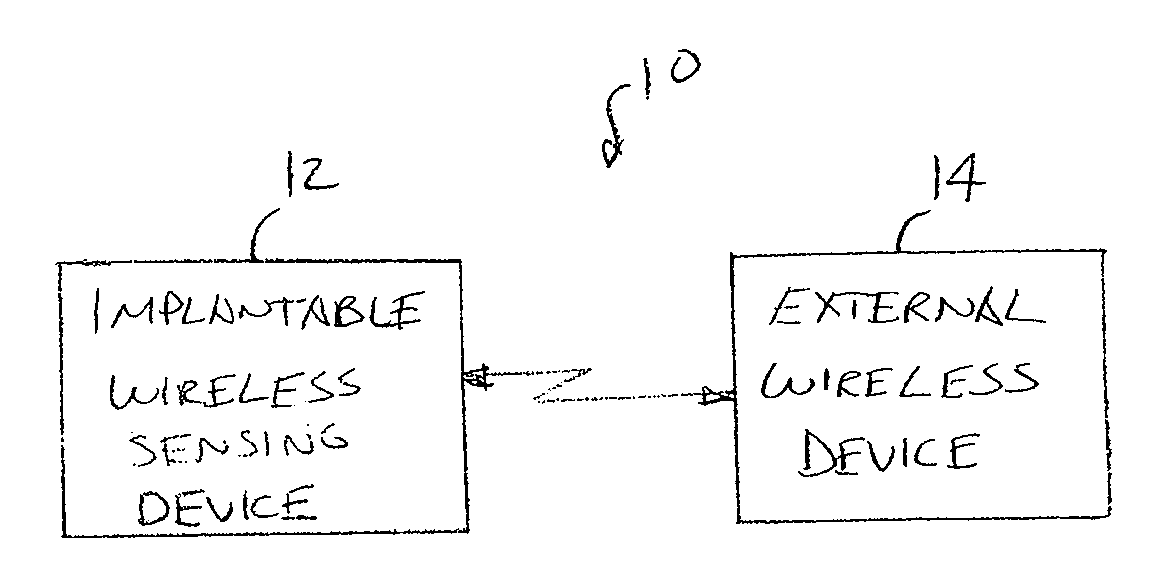
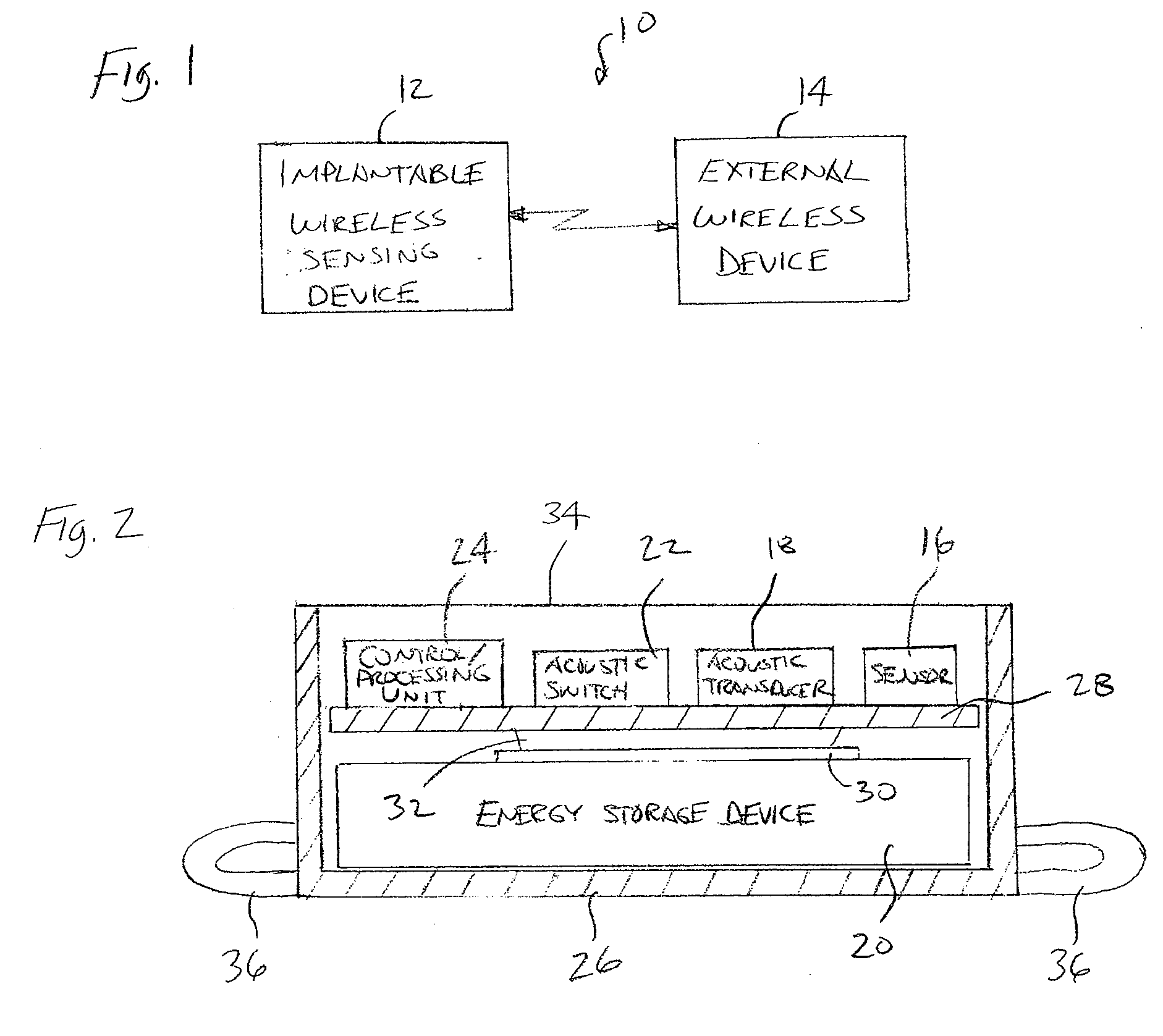
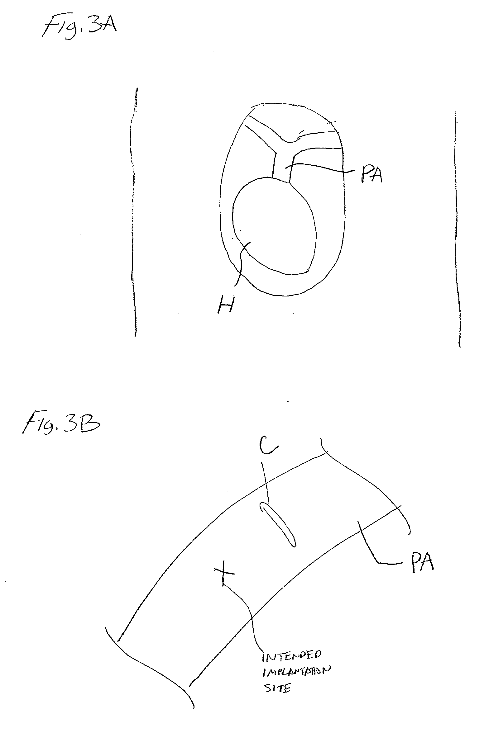
[0030]Referring to FIG. 1, an implantable system 10 constructed in accordance with one embodiment of the present inventions will now be described. The implantable system 10 generally comprises an implantable sensing device 12, which is configured for being implanted within and acquiring physiological information from a patient, and an external device 14 configured for wirelessly interacting with the sensing device 12. As will be described in further detail below, the sensing device 12 is designed to be implanted within an anatomical vessel (e.g., a pulmonary artery) of a patient during a surgical procedure performed to repair or replace an anatomical structure (e.g., a heart), so that a physiological parameter (e.g., blood pressure) can be measured to post-operatively monitor the patient.

[0031]In the illustrated embodiment, the external device 14 is a handheld battery operated unit. Because the sensing device 12 is intended to be implanted deep within the tissue of the patient, the ...


PUM


Abstract

A method of implanting a wireless device within a patient is provided. The wireless device is capable of wirelessly communicating within another device (e.g., an external device) using, e.g., acoustic energy, electromagnetic energy, or magnetic energy. The method comprises forming a surgical opening within the patient to expose an anatomical structure, and repairing or replacing the anatomical structure. The method further comprises introducing the wireless device into an anatomical cavity (e.g., a blood vessel or a heart chamber) via the surgical opening. The method further comprises affixing the wireless device within the anatomical cavity (e.g., using the securing means set forth above), wherein the entire device is contained within the anatomical cavity.

Description

CROSS-REFERENCE TO RELATED APPLICATIONS [0001]This application claims the benefit under 35 U.S.C. § 119 to U.S. Provisional Application Ser. No. 60 / 803,023, filed on May 23, 2006, which is incorporated herein by reference.BACKGROUND OF THE INVENTION [0002]A surgical procedure can be performed on a patient either to remove or repair a portion of the patient's body or to determine whether disease is present in the patient's body. One surgical procedure can be a surgical cardiac procedure, for example, one that involves coronary bypass grafting or a surgical valve replacement or repair. Some patients undergoing cardiac surgery are considered to be at high risk for the postoperative period and are kept under close observation for up to several weeks after surgery.[0003]The monitored vital parameters of these patients include hemodynamic parameters, which are crucial in those patients suffering from cardiovascular disease. The most significant hemodynamic parameters monitored include lef...

Claims


Application Information

Patent Timeline
IPC IPC(8): G06K9/00
CPCA61B5/0031G06K9/00885A61B5/412G06V40/10
Inventor PENNER, ABRAHAM
Owner REMON MEDICAL TECH
Why Eureka
Try Eureka