

System and method to identify and measure organ wall boundaries
a technology of organ wall and boundary, applied in the field of ultrasound-based diagnostic systems and procedures, can solve the problems of inaccurate border detection and prevent an accurate assessment of a true medical condition, and achieve the effect of accurate detection and delineation
- Summary
- Abstract
- Description
- Claims
- Application Information
AI Technical Summary
Benefits of technology
Problems solved by technology
Method used
Image

Examples
Embodiment Construction
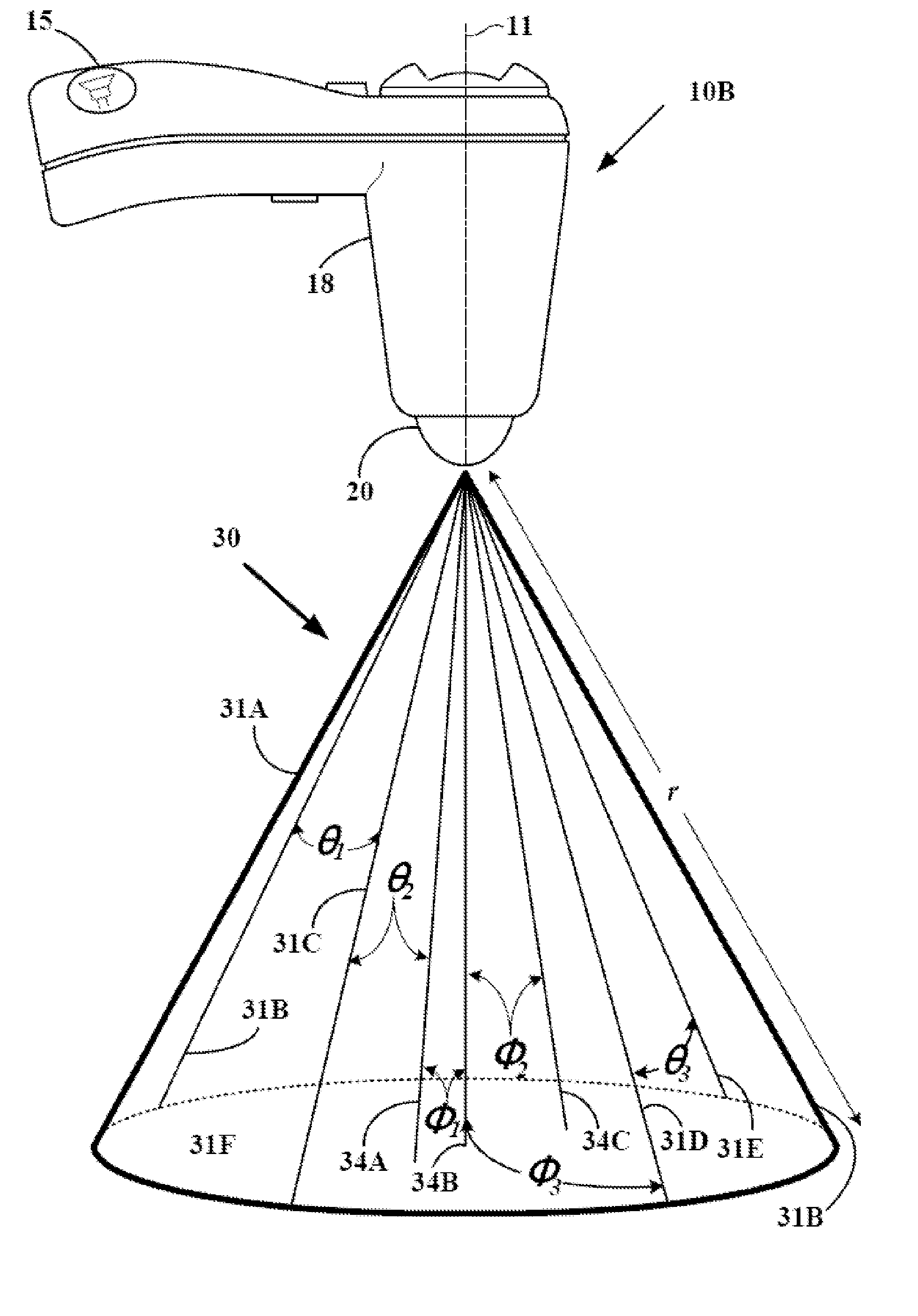
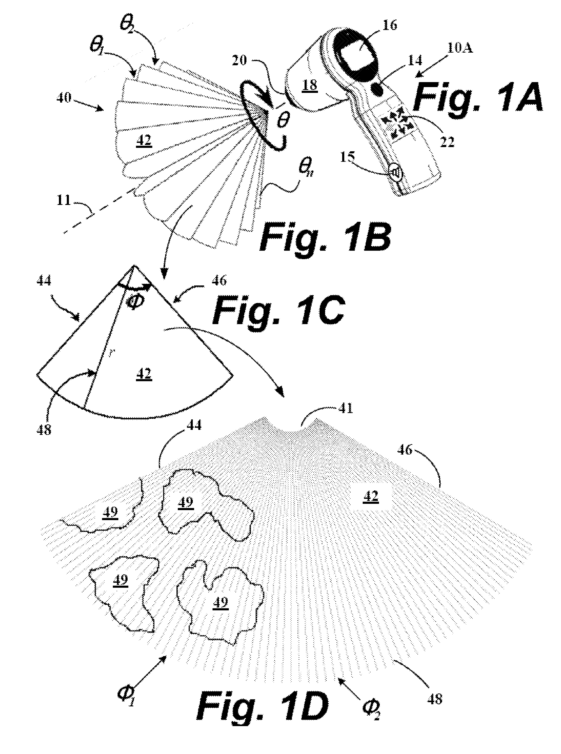
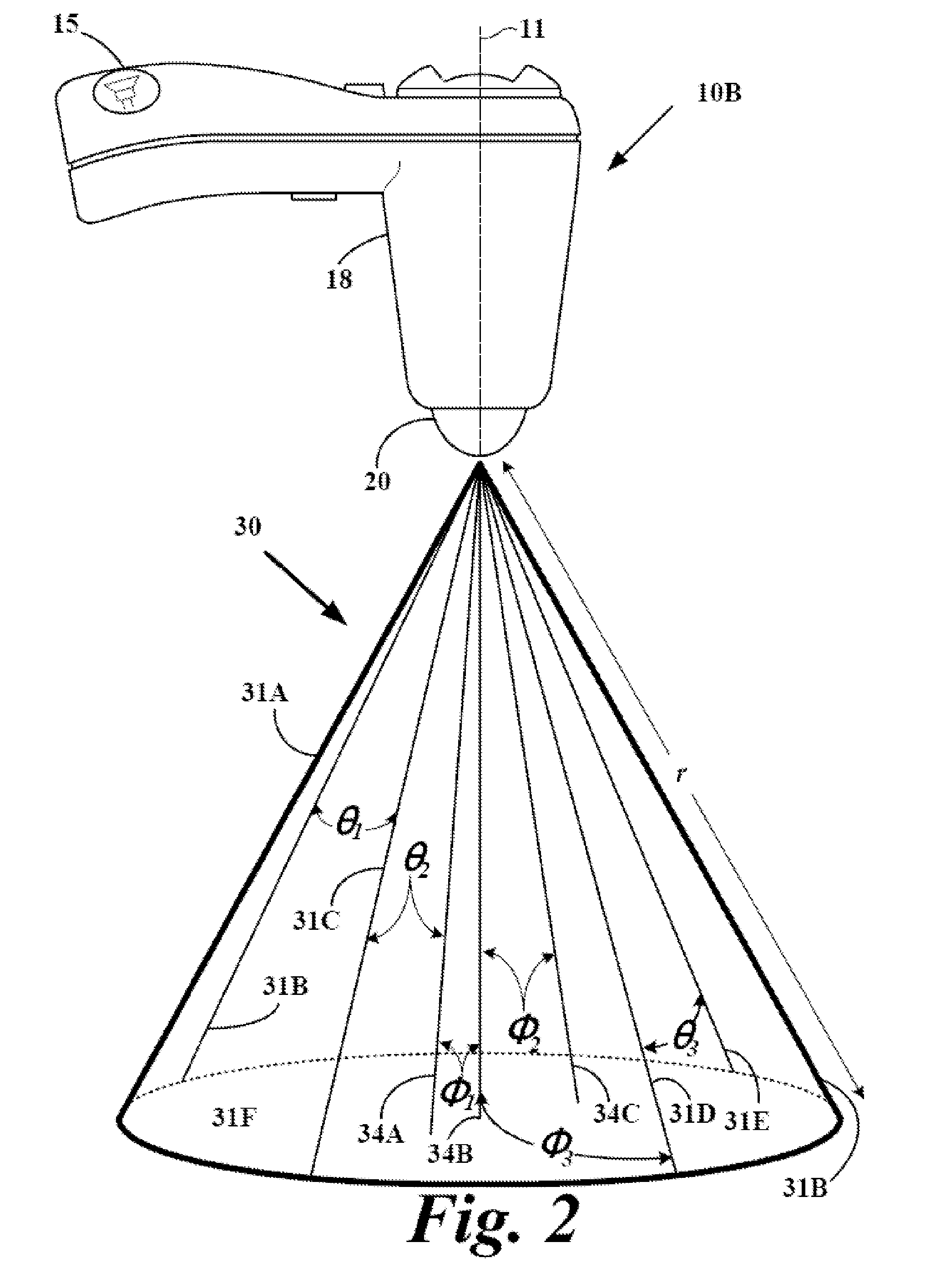
[0017] Ultrasound systems and methods to dynamically develop and present 2D and 3D images of a cavity structure within a region-of-interest (ROI) that is either partially or completely surrounded by echogenic tissue to permit the accurate detection and delineation of close contours of a cavity-tissue interface in the wall region of an organ or structure. The ultrasound systems and algorithmic methods are adapted to detect and segment cavities according to the shape of the cavity and the degree to which the cavity is surrounded by higher echogenic tissue by dynamically analyzing pixel groups near the cavity-tissue interface. The transceivers used by the ultrasound systems vary in the fundamental frequency used for probing the ROI. The algorithms vary as to which fundamental or harmonic frequency is used for imaging and whether the cavity is substantially spherical or substantially non-spherical.
BRIEF DESCRIPTION OF THE DRAWINGS
[0018] The file of this patent contains at least one dra...
PUM
 Abstract
Description
Claims
Application Information