Navigation system for position self control robot and floor materials for providing absolute coordinates used thereof

a technology of positioning self control and floor materials, which is applied in the direction of distance measurement, reradiation, instruments, etc., can solve the problems of decreasing accuracy, accumulating measurement errors, and reducing accuracy of method using rfid, so as to achieve fast and accurate calculation or recognition, easy acquisition, and reliably controlling a moving direction

Inactive Publication Date: 2007-11-29
MICROROBOT
View PDF4 Cites 92 Cited by
  • Summary
  • Abstract
  • Description
  • Claims
  • Application Information

AI Technical Summary

Benefits of technology

[0016] The present invention provides a navigation system by which a current position (i.e., an absolute coordinate value) of a position self control robot is prevented from being interfered with an identification unit corresponding to an adjacent absolute coordinate value to easily acquire the current position of the position self control robot, when an obstacle is recognized within a predetermined area, relative coordinate value of the obstacle and a distance between the exact current position of the position self control robot and the obstacle are quickly and accurately calculated or recognized to reliably control a moving direction and distance of the position self control robot, different unique position information is easily installed in any place, and maintenance is facilitated.

Problems solved by technology

However, since the odometry calculates a position and a direction using integration, as a traveling distance increases, a measurement error is accumulated.
In particular, an error occurring due to slippage that may occur due to a floor material in a move area is accumulated without being compensated for, thereby decreasing accuracy.
Such restriction causes the accuracy of the method using the RFID to decrease.
In addition, an error may also occur when a substance absorbing a magnetic field is present in a place where the RFID cards 3 are laid.
When the distribution density of the RFID cards 3 is not high enough, recognition of the direction becomes difficult.
In particular, it is inconvenient to lay the RFID cards 3 in the floor 5.
Furthermore, since in a wide area, a lot of RFID cards 3 need to be used, high installation cost and high maintenance cost are incurred and careful treatment is needed during maintenance in operating the position self control robot 1.

Method used


Image

  • Navigation system for position self control robot and floor materials for providing absolute coordinates used thereof
  • Navigation system for position self control robot and floor materials for providing absolute coordinates used thereof
  • Navigation system for position self control robot and floor materials for providing absolute coordinates used thereof

Examples


first embodiment

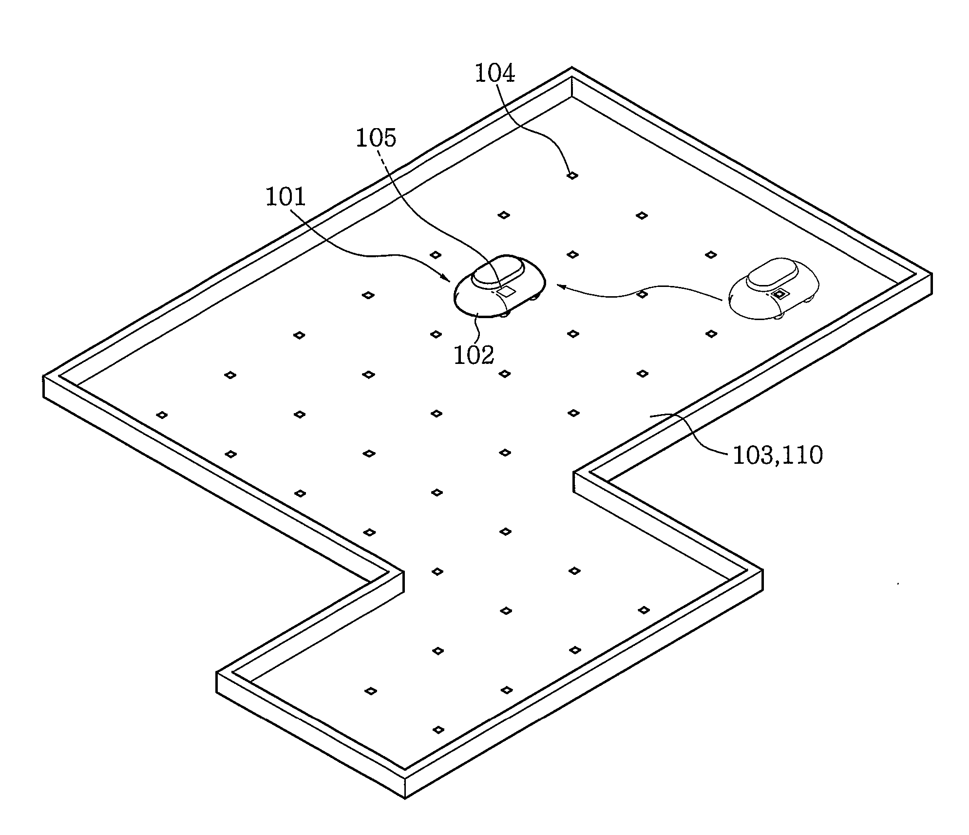
[0060] Meanwhile, a floor material 110 includes the 2D barcode 104. In the floor material 110 shown in FIG. 7A according to the present invention, a plurality of 2D barcodes 104 respectively having different unique coordinate values are reversely printed at predetermined intervals on a rear side of a first sheet 111 made of a transparent material having a predetermined area.

[0061] Additionally, when a protective layer 114 is provisionally attached to an adhesive layer 111a, the first sheet 111 can be immediately and conveniently used by simply removing the protective layer 114.

[0062] For example, when the 2D barcodes 104 are printed in all directions at an interval of 30 cm on the first sheet 111 having a size of 180×180 cm in length and width, six 2D barcodes 104 are printed in each of lengthwise and widthwise directions. The 2D barcodes 104 may have position information like (0,0), (0,1), (0,2), (0,3), (0,4), (0,5), (1,0), (1,1), . . . , (5,4), (5,5). Such arrangement and design ...

third embodiment

[0067] Invisible transparent or secret ink used in the first through third embodiment of the present invention is typically used at present. When the invisible transparent or secret ink is used, a sign (including a number), a character, or a figure printed on security paper and securities such as paper money, bills, and gift certificates is not visible and cannot be copied or scanned.

[0068] The secret ink may be an organic fluorescent material, a quencher, or a cured resin composite, which emits 651-900 nm wavelength light in response to 300-850 nm wavelength light. Alternatively, the secret ink may be manufactured by making 1-litter A solution by mixing EC (i.e., 2-ethoxyethanol expressed by a molecular formula C4H1002) with methyl alcohol (MT) in proportion of 40-20% and by mixing the A solution with a 130-170 g CKR (i.e., a MgO reactive alkyl phenolic resin), 15-25 cc OX (C17H23CO2H), and 0.01-0.001 g Si. The present invention is not restricted thereto. However, the transparent o...

second embodiment

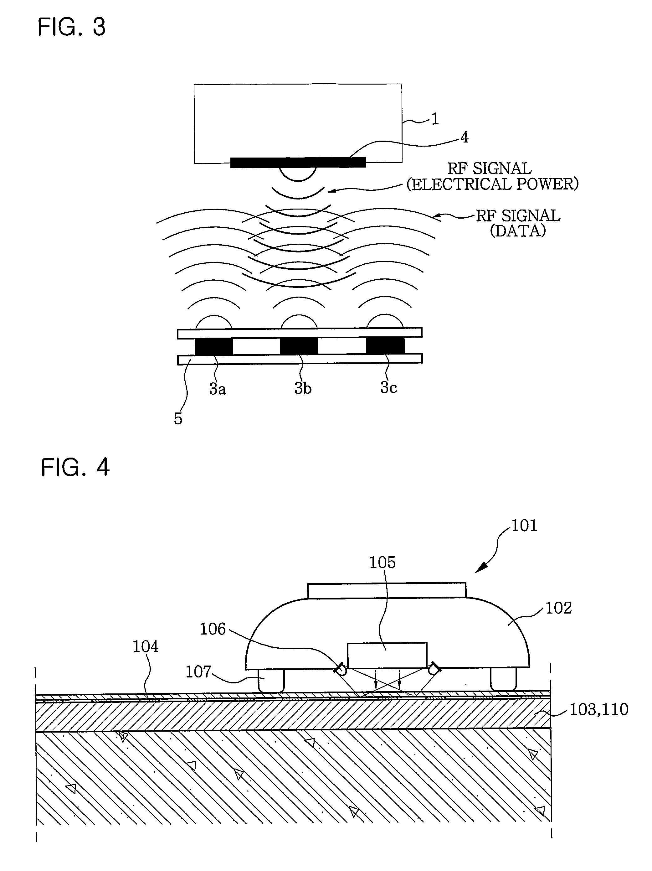
[0071] Referring to FIGS. 8A through 8C, which illustrates the floor material 110, a single 2D barcode 104 having a unique coordinate value is printed on a rear side of the second sheet 112 made of a transparent material and an adhesive layer 112a is formed on the rear side on which the 2D barcode 104 is printed. A plurality of the second sheets 112 are directly bonded to the floor material 110.

[0072] Additionally, a protective layer 114 may be provisionally attached to the adhesive layer 112a so that the second sheet 112 can be immediately bonded to the floor material 110 after the protective layer 114 is removed.

[0073] In the second embodiment of the present invention, when the barcode reader 105 of the position self control robot 101 cannot recognize a unique coordinate value of the 2D barcode 104 damaged due to damage to the surface of the floor material 110, the damaged second sheet 112 can be easily replaced with a new one. Since only a small damaged portion can be easily rep...


PUM

PropertyMeasurementUnit
wavelength rangeaaaaaaaaaa
sizeaaaaaaaaaa

Abstract

A navigation system for a position self control robot including a main body having a locomotion unit is provided. The navigation system includes two-dimensional (2D) barcodes, a barcode reader, and a control unit. The 2D barcodes are formed at predetermined intervals on a floor having a predetermined size and respectively have different unique coordinate values. The barcode reader is installed at a predetermined position in a lower portion of the main body to read a 2D barcode on the floor. The control unit is installed at the main body to be electrically connected with the barcode reader, recognizes absolute coordinates within a predetermined area, which are stored in memory, based on a unique coordinate value of the 2D barcode read by the barcode reader, applies the absolute coordinates to a programmed locomotion algorithm, and controls the locomotion unit to move the main body.

Description

TECHNICAL FIELD [0001] The present invention relates to a navigation system for a position self control robot having a main body with a locomotion unit, and more particularly, to a navigation system that acquires an exact current position of a position self control robot which is moving or operating and that quickly calculates a relative distance between the position self control robot and each of a predetermined obstacle and a predetermined move restriction line to enable the position self control robot to quickly and accurately move in accordance with a programmed locomotion algorithm or a stored traveling path. In addition, the present invention relates to a floor material for providing absolute coordinates, which includes two-dimensional (2D) barcodes having different unique coordinate values at predetermined intervals to enable the position self control robot to quickly acquire a current absolute position, where the 2D barcodes does not show color at visible rays but show color...

Claims


Application Information

Patent Timeline
Patent Type & Authority Applications(United States)
IPC IPC(8): G05D1/02B41M5/00G01S13/82
CPCG01S13/825G05D2201/0211G05D1/0272G05D1/0236
Inventor KIM, KYEONG-KEUN
Owner MICROROBOT
Why Eureka
Try Eureka