Electromagnetically determining the relative location of a drill bit using a solenoid source installed on a steel casing

a solenoid source and magnetic determination technology, applied in the direction of borehole/well accessories, survey, etc., can solve the problems of insufficient control, insufficient control, and inability to provide precise control, etc., to achieve the effect of long rang

Active Publication Date: 2007-12-06
HALLIBURTON ENERGY SERVICES INC
View PDF9 Cites 182 Cited by
  • Summary
  • Abstract
  • Description
  • Claims
  • Application Information

AI Technical Summary

Benefits of technology

[0008]The characteristic magnetic field is generated through the use of one or more electrically powered electromagnetic field beacons installed in the first well and is measured by a down-hole measurement while drilling (MWD) electronic survey instrument in the second borehole. The first borehole may be a reference well, while the MWD instrument may be near the drill bit in a borehole being drilled. Each magnetic field source beacon consists of a coil of wire wound on a steel coupling between two lengths of steel tubing in the reference well, and powered by an electronic package. Control circuitry in the electronic package continuously “listens” for, and recognizes, a “start” signal that is initiated by the driller. After a “start” signal has been received, the beacon is energized for a short time interval during which an electromagnetic field is generated, which is measured by the measurement while drilling apparatus. Switching circuitry periodically reverses the direction of the generated electromagnetic field, and the measured vector components of the electromagnetic field are used to determine the relative location coordinates of the drilling bit and the beacon using well-known mathematical methods.
[0010]In accordance with a second aspect of the invention, a method for measuring the distance and direction between two boreholes extending into the Earth comprises the steps of installing a solenoid assembly at a first selected point in a first borehole, wherein the first borehole has a known inclination and direction at the selected point, and deploying a magnetic field sensor at a second selected point in a second borehole for measuring magnetic field and gravity vector components at the second point. The spatial orientation of the magnetic field sensor is determined, and electronic circuitry is provided in the solenoid assembly that actively waits for an initiating signal. A remote transducer sends an initiating signal under the control of the drill controller, and this starts a prescribed electric current flow into the solenoid to generate its characteristic known solenoid field for a short interval of time.

Problems solved by technology

Even though the guidance of boreholes with respect to existing wells is, in general, well developed, special problems can occur where existing techniques are not sufficient to provide the precise control that is required for that situation.
For example, when it is desired to locate and to either avoid or to intersect a particular target well in a field that includes numerous other wells, problems can occur.
Problems of tracking and guidance are also encountered when drilling non-parallel wells, such as drilling a horizontal well through a field of vertical wells, or vice versa, where it is desired to avoid the existing wells, or, in the alternative, where it is desired to intersect a specific well.
Another area of difficulty occurs in the drilling of multiple horizontal wells, particularly where a well being drilled must be essentially parallel to an existing well.

Method used


Image

  • Electromagnetically determining the relative location of a drill bit using a solenoid source installed on a steel casing
  • Electromagnetically determining the relative location of a drill bit using a solenoid source installed on a steel casing
  • Electromagnetically determining the relative location of a drill bit using a solenoid source installed on a steel casing

Examples


Embodiment Construction

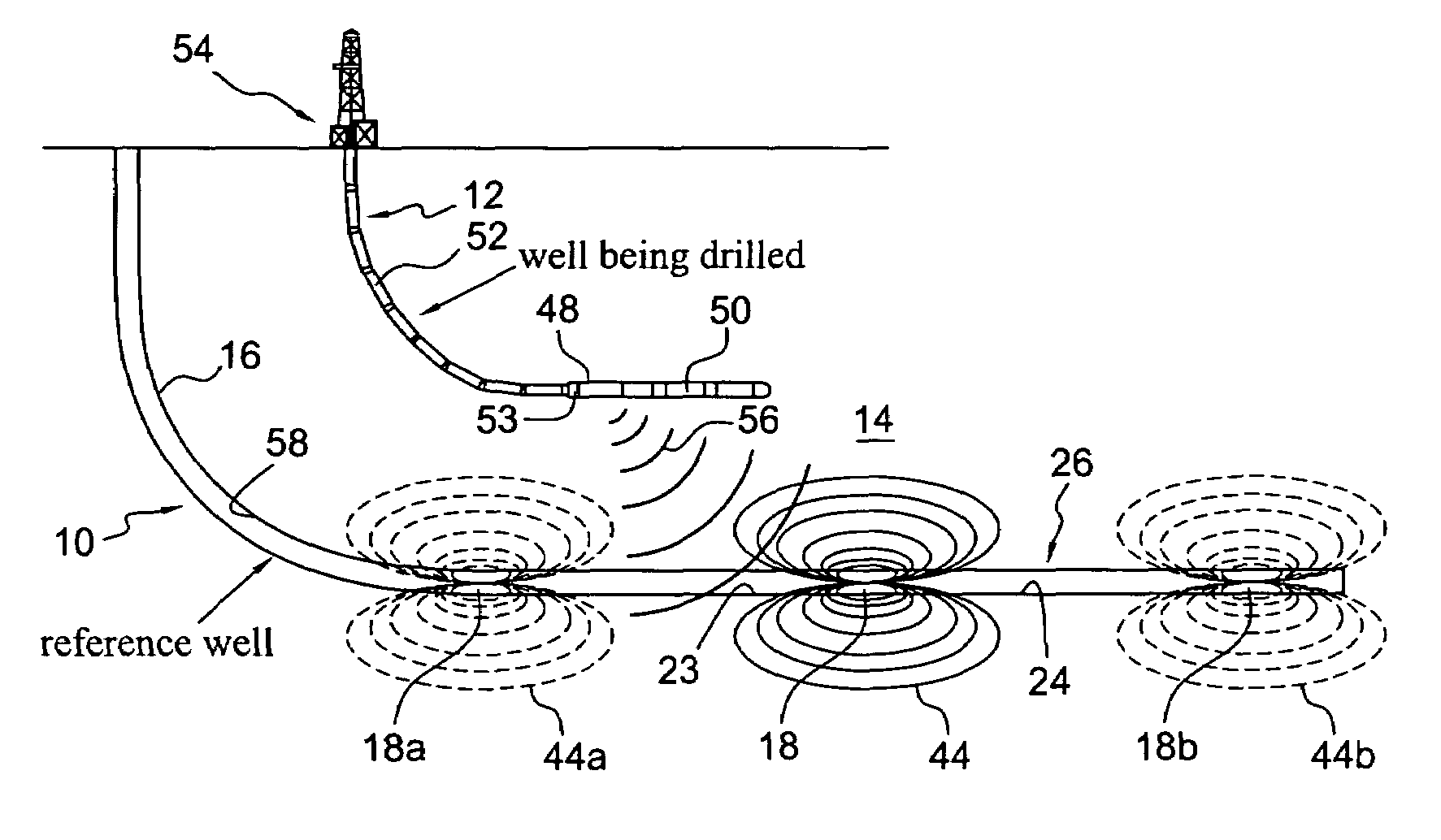
[0024]Turning now to a more detailed description of the present invention, there is illustrated in FIG. 1 an overall view of a pair of wells 10 and 12 in an oil field 14 for use in SAGD (steam assisted gravity drainage) production of oil from a non-flowing bitumen hydrocarbon formation. As illustrated, well 10 is a previously drilled and cased horizontal well which serves as a reference well, while well 12 is being drilled along a path that is near, and parallel to, a horizontal portion of the first well. In this important SAGD application, steam will be injected into the upper well 12 to melt the bitumen to allow it to flow to the lower well 10, from which it is pumped to the Earth's surface. An important specification of such a well pair is that the horizontal portions of the pair, which are located in the hydrocarbon formation, must be precisely parallel to each other, with a precisely specified separation. Typically, the well pair will have a horizontal reach of 1.5 km with a se...


PUM


Abstract

Electrically powered electromagnetic field source beacons installed in a reference well in combination with a down-hole measurement while drilling (MWD) electronic survey instrument near the drill bit in the borehole being drilled permit distance and direction measurements for drilling guidance. Each magnetic field source beacon consists of a coil of wire wound on a steel coupling between two lengths of steel tubing in the reference well, and powered by an electronic package. Control circuitry in the electronic package continuously “listens” for, and recognizes, a “start” signal that is initiated by the driller. After a “start” signal has been received, the beacon is energized for a short time interval during which an electromagnetic field is generated, which is measured by the MWD apparatus. The generated magnetic field may be an AC field, or switching circuitry can periodically reverse the direction of a generated DC electromagnetic field, and the measured vector components of the electromagnetic field are used to determine the relative location coordinates of the drilling bit and the beacon using well-known mathematical methods. The magnetic field source and powering electronic packages may be integral parts of the reference well casing or may be part of a temporary work string installed therein. Generally, numerous beacons will be installed along the length of the reference well, particularly in the important oil field application of drilling steam assisted gravity drainage (SAGD) well pairs.

Description

[0001]This application claims the benefit of U.S. Provisional Application No. 60 / 810,696, filed Jun. 5, 2006 and of U.S. Provisional Application No. 60 / 814,909, filed Jun. 20, 2006, the disclosures of which are hereby incorporated herein by reference.BACKGROUND OF THE INVENTION[0002]The present invention is directed, in general, to a method and apparatus for tracking the drilling of boreholes at a substantial depth in the earth, and more particularly to methods for determining the relative location of a reference well from a borehole being drilled through the use of a beacon located on the reference well casing.[0003]The difficulties encountered in tracking and guiding the drilling of a borehole that is intended to intersect, to avoid, or to drill on a precise predetermined path to, a reference well at great depth below the surface of the earth are well known. Such guidance may be required, for example, when it is desired to construct a complex underground “plumbing system” for the ...

Claims


Application Information

Patent Timeline
Patent Type & Authority Applications(United States)
IPC IPC(8): E21B47/18
CPCE21B47/024E21B47/02216E21B47/0228
Inventor KUCKES, ARTHUR F.PITZER, RAHN
Owner HALLIBURTON ENERGY SERVICES INC
Why Eureka
Try Eureka