[0012] This task is accomplished by the invention, proceeding from an earthquake
alert system of the type stated initially, in that the
system comprises at least two detection units that each have a tremor sensor and electronic
signal processing means, in each instance, whereby the
signal processing means of each detection unit are set up in such a manner that they detect primary waves of earthquakes on the basis of the signal of the tremor sensor, and whereby the detection unit are connected with one another by way of an
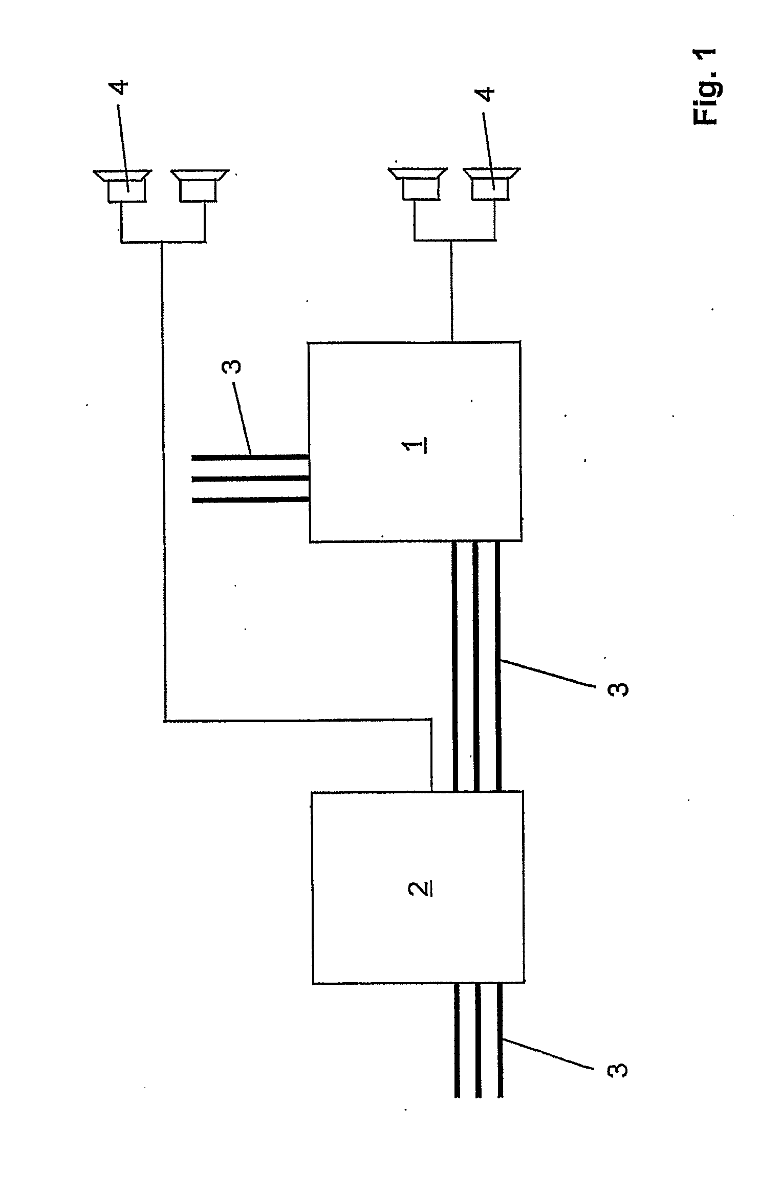
electronic data bus. The invention is based on the recognition that a reliably functioning and thereby safe earthquake alert system can be created if it is structured by means of two or more functionally reliable detection units that are separate and independent of one another. A
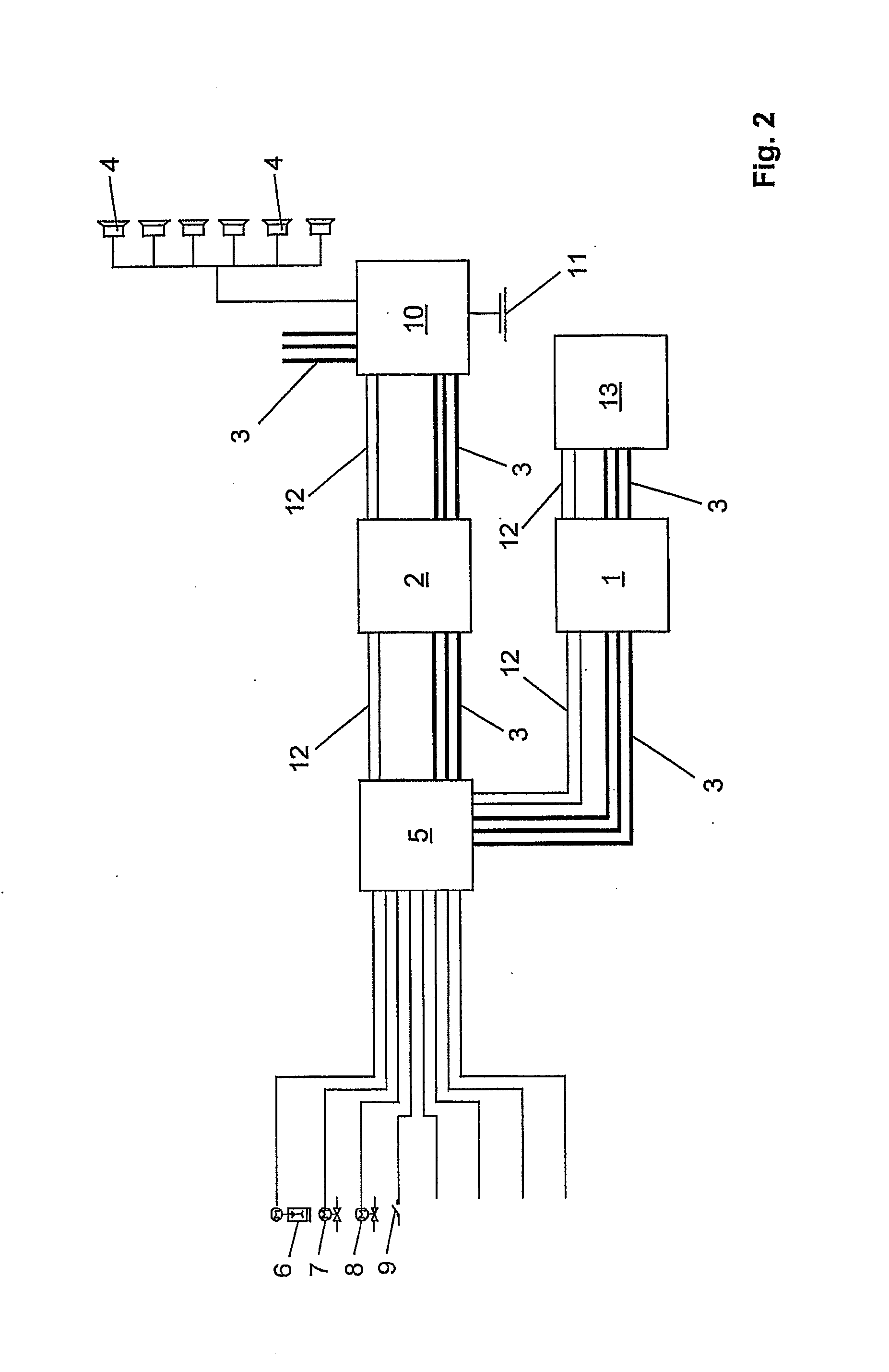
significant difference of the system according to the invention as compared with the state of the art specifically consists in the fact that each of the two or more detection units has at least one tremor sensor as well as its own electronic signal processing means for processing and analyzing the ground tremor signals recorded by the tremor sensor, in each instance, assigned to it, in each instance. In this way, each detection unit is able to detect P waves of potentially hazardous earthquakes. The desired redundancy results from the fact that the individual detection units of the system according to the invention are connected with one another by way of an
electronic data bus. The detection units can communicate with one another via this data bus, so that it can be determined, for example, whether two or more of the detection units have agreed in detecting a
P wave. In the case of the earthquake alert system according to the invention, triggering of an alarm can be made dependent on this, particularly in order to avoid false alarms. A significant
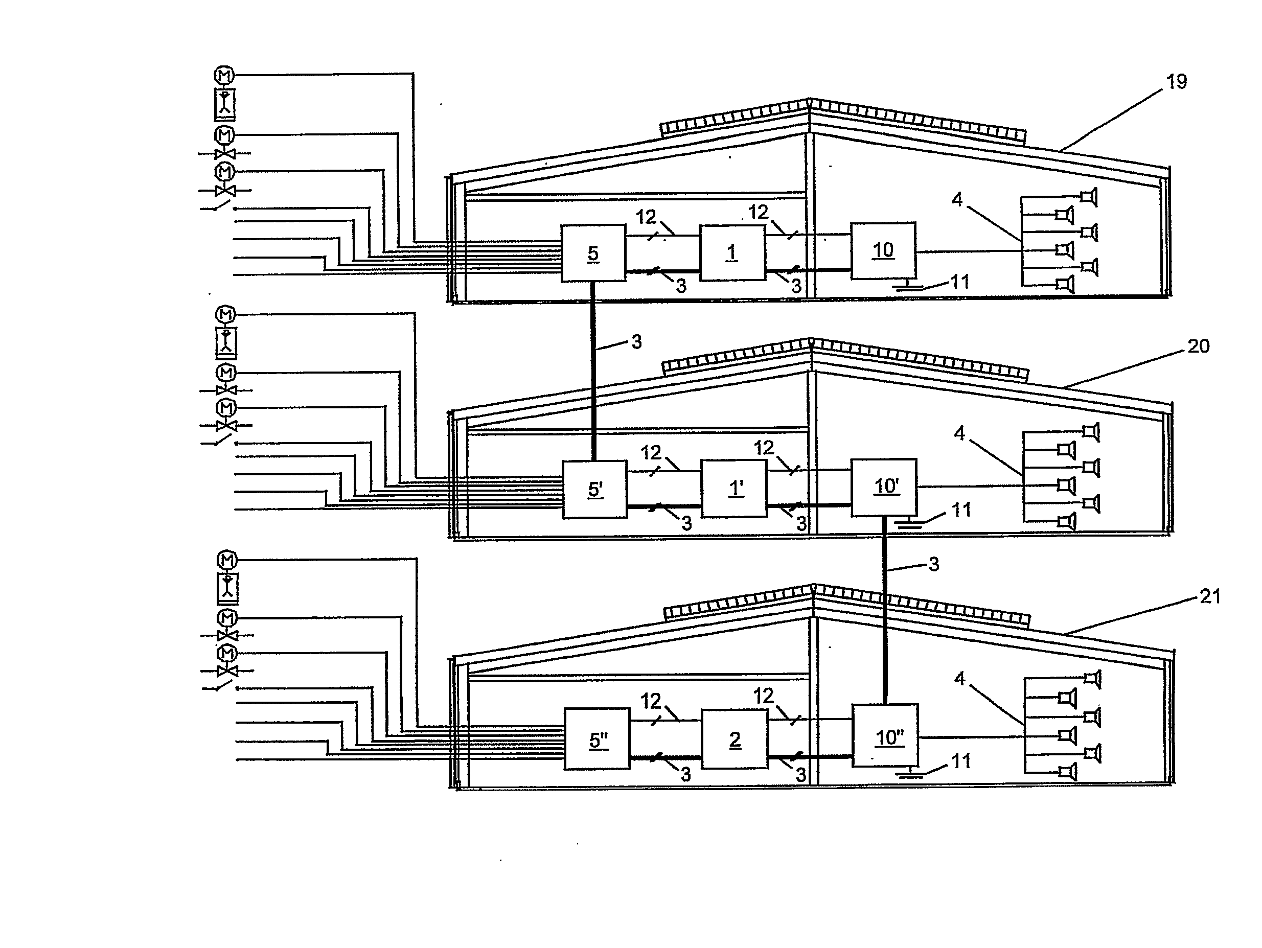
advantage of the earthquake alert system according to the invention is that it can be expanded and scaled as desired. A reliable earthquake alert, resistant to false alarms, is already possible by means of only two detection units. By adding additional detection units, the safety can be increased, so that even if individual detection units fail, sufficient reliability is still guaranteed. Furthermore,
scalability is advantageous if a step-by-step structure of the earthquake alert system is desired in large buildings or building complexes.
[0013] The
modular structure of the earthquake alert system according to the invention furthermore has the
advantage that any desired type of buildings and building complexes can be monitored by means of standardized detection units that are connected with one another by way of the electronic data bus, inexpensively and, at the same time, with a high degree of safety. It has proven to be particularly practical if characteristic variables are calculated from the tremor signals of primary waves that are detected, by means of the signal processing means of the detection units according to the invention, which variables are a measure of the destructive effect of secondary waves to be expected subsequently. An alarm can then be given as a function of the result of a comparison of the calculated characteristic variables with corresponding threshold values. In the case of the system according to the invention, it is practical if tremor sensors are used to detect acceleration values in three spatial directions. The Corresponding signals can then be calculated into a characteristic variable, taking into consideration the
frequency spectrum and weighting the acceleration components detected in the three spatial directions. This number can then be compared, in simple manner, with a threshold value, whereby this threshold value indicates the value from which an
S wave that could have destructive effects has to be expected, on the basis of the recorded
P wave. According to the invention, therefore, not only is a
P wave detected, but it is also assessed. This method of procedure has the
advantage, as compared with the systems known from the state of the art, that an alarm will reliably be triggered only if danger is actually a
threat. In typical earthquake regions, small earth tremors occur practically every day. Using the system according to the invention, it is possible to avoid constantly and unnecessarily giving an alarm in these regions. Constant false alarms would have the result, within a short period of time, that alarms of the alert system would not be taken seriously. The final result would be a complete lack of acceptance of the system.
[0014] The electronic data bus of the system according to the invention can be implemented conventionally, by means of corresponding
data lines in the form of cable connections. However, it is also particularly advantageous to implement the data bus as a whole, or at least parts of the corresponding signal transmission paths, by way of
wireless connections. Suitable standard components for
wireless digital signal transmission are commercially available at low costs nowadays. A
wireless data bus makes it possible, in advantageous manner, to install the earthquake alert system according to the invention in cost-effective manner, with the lowest possible expenditure. Particularly if building complexes of several separate buildings are supposed to be monitored, wireless connections are obviously particularly practical.


