Protection device

a technology of protection device and shielding device, which is applied in the direction of pulse manipulation, pulse technique, electrical apparatus, etc., can solve the problems of not being able to eliminate bounce, circuit damage and misoperation of electronic devices, and damage to electronic devices, etc., and achieve the effect of simplified software design and hardware circui

Inactive Publication Date: 2007-12-06
INVENTEC CORP
View PDF5 Cites 9 Cited by
  • Summary
  • Abstract
  • Description
  • Claims
  • Application Information

AI Technical Summary

Benefits of technology

[0014]Compared with the prior art, through operation between the setting unit and the processing unit, the protection device of the present invention can transfer a multi-pulse on / off signal which is produced by continuous pressing the power button in a determined time to a single-pulse signal which triggers the electronic device to do a normal power switching operation.
[0015]Furthermore, the hardware circuit of the present invention is simple and can be applied to different electronic devices only by changing the charging and discharging time value of the resistance and the capacitance, thus the software design of the electronic device is simplified.

Problems solved by technology

That is to say, continuous and instantaneous on and off may be produced to trigger the electronic device, thereby circuit damage and misoperation of the electronic device may occur.
The manmade bounce refers to frequently pressing the button in a short time by a user, which may also result in circuit damage and misoperation.
However, as the EC 11 is generally a 16-bit Micro Control Unit (MCU) with short timing pulse, the debounce program can only eliminate bounce in tens of millisecond (ms), thereby the aforementioned method can only eliminate bounce caused by the mechanical bounce and can not be applied to eliminating bounce caused by the manmade bounce because a time interval of the manmade bounce is as high as hundreds of milliseconds.
Therefore, pressing power button continuously may induce misoperation of system power on timing, cause circuit damage or misoperation, and more seriously result in system downtime.
Furthermore, the debounce time range is fixed because the debounce program is stored in the EC 11, so a software designer must rewrite the debounce program according to different Notebook and button with different bounce time range, thereby complexity of software design is increased.

Method used


Image

  • Protection device
  • Protection device
  • Protection device

Examples


Embodiment Construction

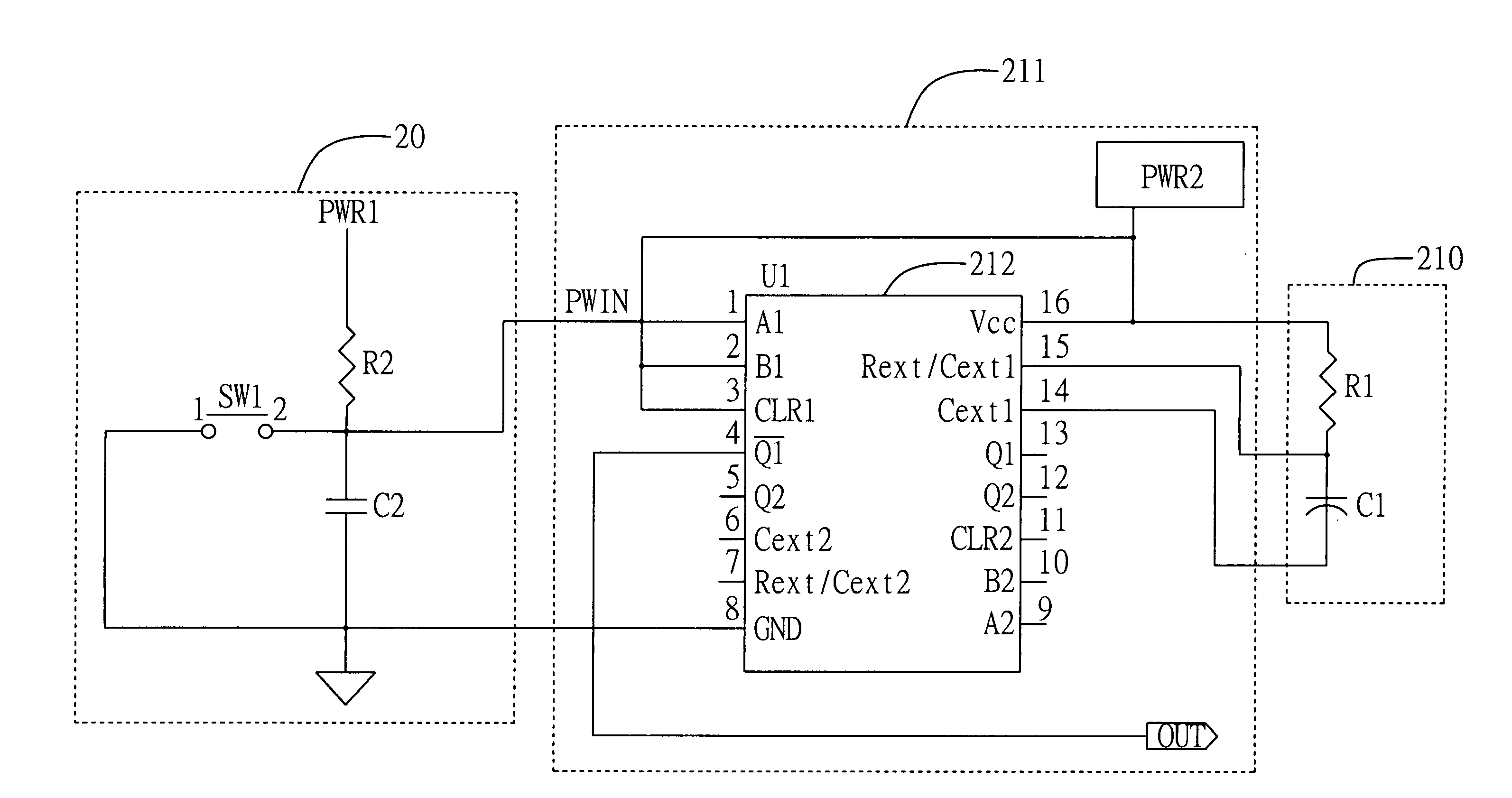
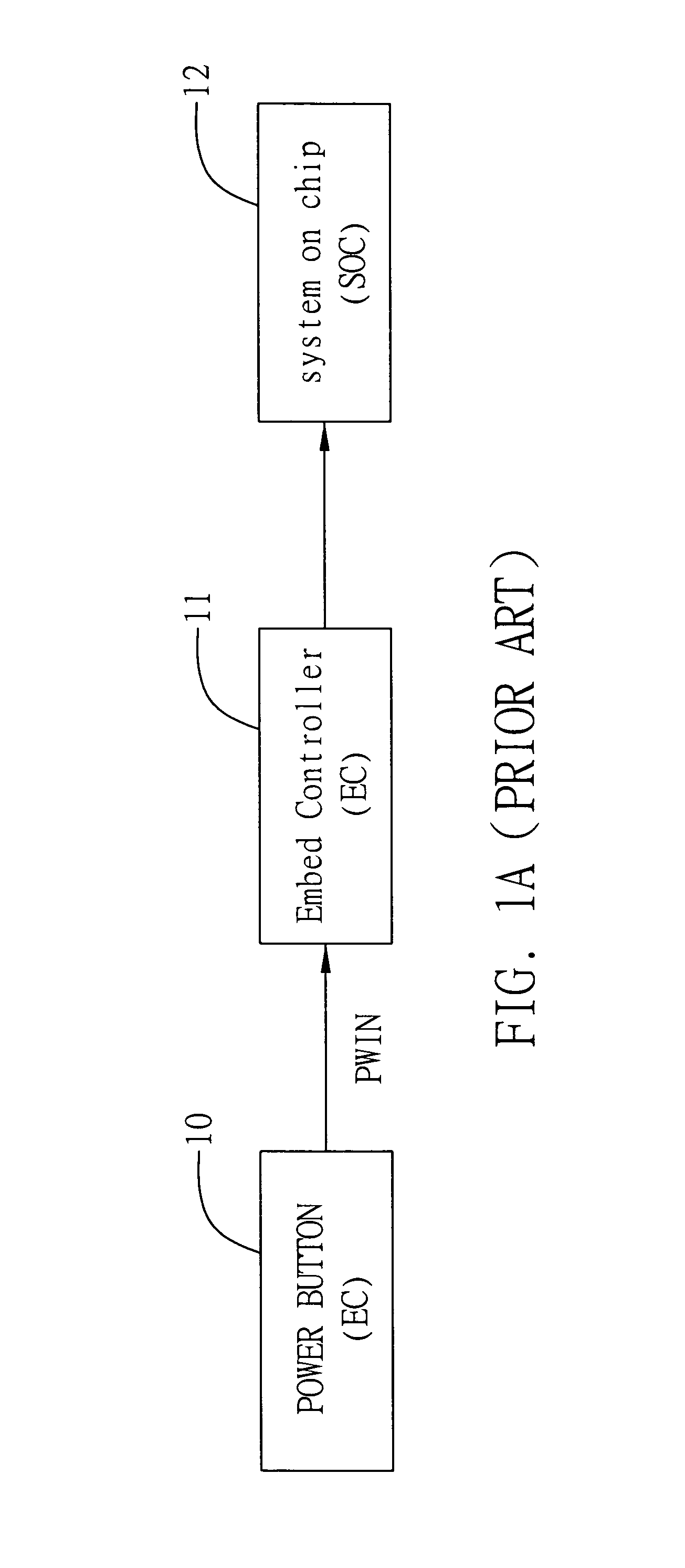
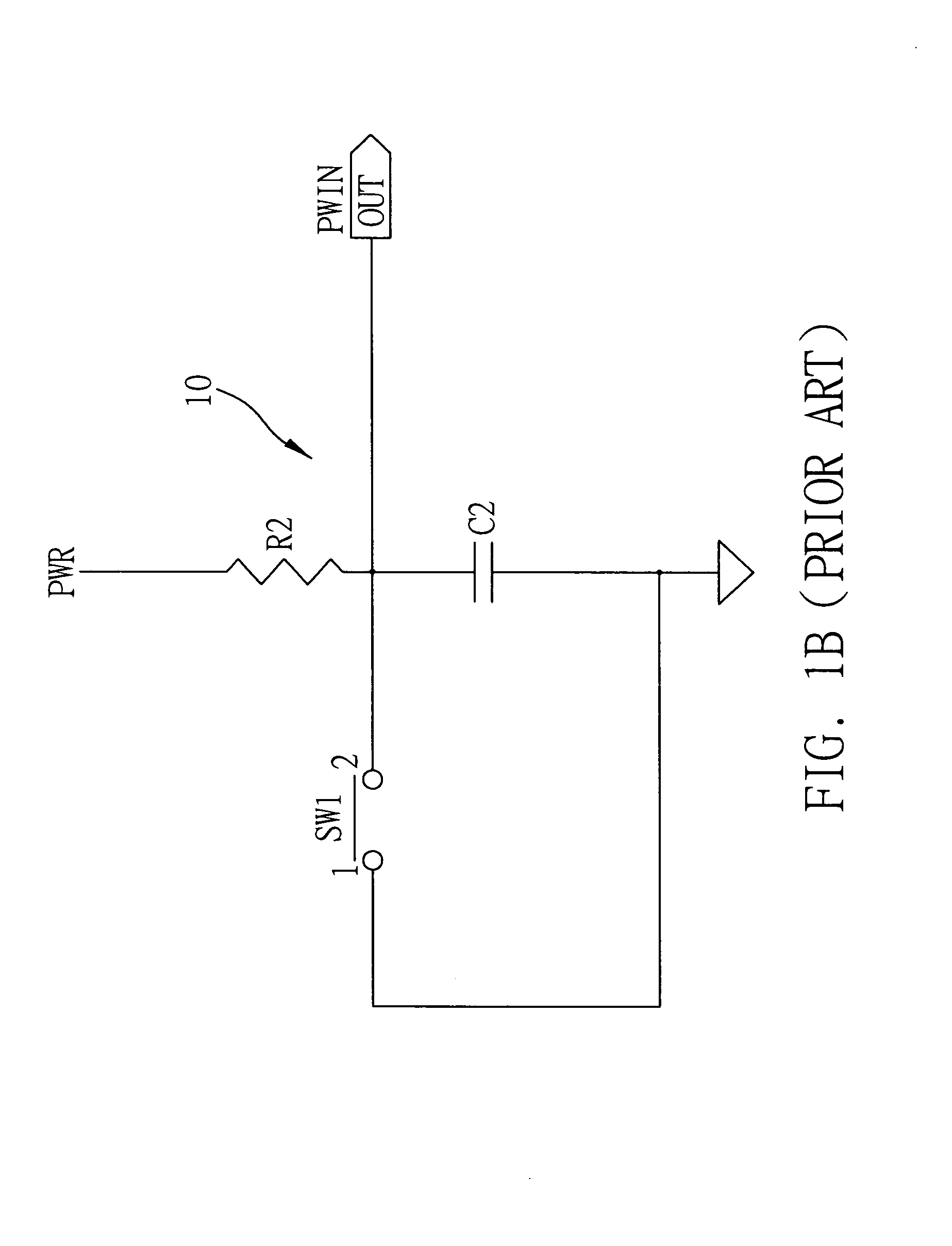
[0022]FIG. 2A is a functional block diagram of an operating unit 20, a system on chip (SOC) 22 and a protection device 2 for power switching according to the present invention. The protection device 2 is applicable to an electronic device (not shown), such as a Notebook computer, a personal computer (PC), a server and so on. The electronic device includes the operating unit 20 and the SOC 22. The operating unit 20 is for a user to turn on or turn off the electronic device. The operating unit 20 outputs an on / off signal when the user turns on / off the electronic device. In the present embodiment, the operating unit 20 is a power button, and outputs an on / off signal (PWIN) which is a low-leveled pulse signal when the power button is pressed.

[0023]As shown in FIG. 2A, the protection device 2 comprises a setting unit 210 and a processing unit 211.

[0024]The setting unit 210 is used for setting a predetermined period (T). The setting unit 210 is a setting circuit composed of a resistor and...


PUM


Abstract

A protection device applicable to an electronic device is disclosed. The electronic device includes an operating unit which outputs an on/off signal when a user turns on/off the electronic device is disclosed. The protection device includes a setting unit for setting a predetermined period, and a processing unit electrically connected to the operating unit and the setting unit. The processing unit outputs a trigger signal to turn on/off the electronic device when receiving an on/off signal provided by the operating unit during the predetermined period, and no longer outputs any trigger signal when receiving the on/off signal again during the predetermined period.

Description

BACKGROUND OF THE INVENTION[0001]1. Field of the Invention[0002]The present invention relates to protection devices, and more particularly, to a protection device which avoids circuit damage, misoperation and downtime of an electronic device induced by continuously turning on and off in a determined time an operating unit which controls the power of the electronic device.[0003]2. Description of Related Arts[0004]As is known, when a button of an electronic device is pressed, a trigger signal is produced to turn on a corresponding timing operation of the electronic device, whereas how to effectively eliminate bounce of a button is a long-term subject in the electronic field.[0005]The bounce of a button is classified into a mechanical bounce and a manmade bounce. The mechanical bounce is caused by mechanical structure of the button. That is to say, continuous and instantaneous on and off may be produced to trigger the electronic device, thereby circuit damage and misoperation of the el...

Claims


Application Information

Patent Timeline
Patent Type & Authority Applications(United States)
IPC IPC(8): H02H3/00
CPCH03K5/1254
Inventor WANG, WEESYKYANG, MICHAEL
Owner INVENTEC CORP
Why Eureka
Try Eureka