
Device and method for controlling power converting device

a power conversion device and power converter technology, applied in the direction of electric generator control, dynamo-electric converter control, dynamo-electric gear control, etc., can solve the problems of radio to produce harsh grating noise, fundamental control frequency switching noise and higher harmonics, and adverse effect on the operation of other vehicle-mounted digital instruments, so as to improve the transient characteristics of output current waveform

Inactive Publication Date: 2007-12-06
NISSAN MOTOR CO LTD
View PDF5 Cites 25 Cited by
  • Summary
  • Abstract
  • Description
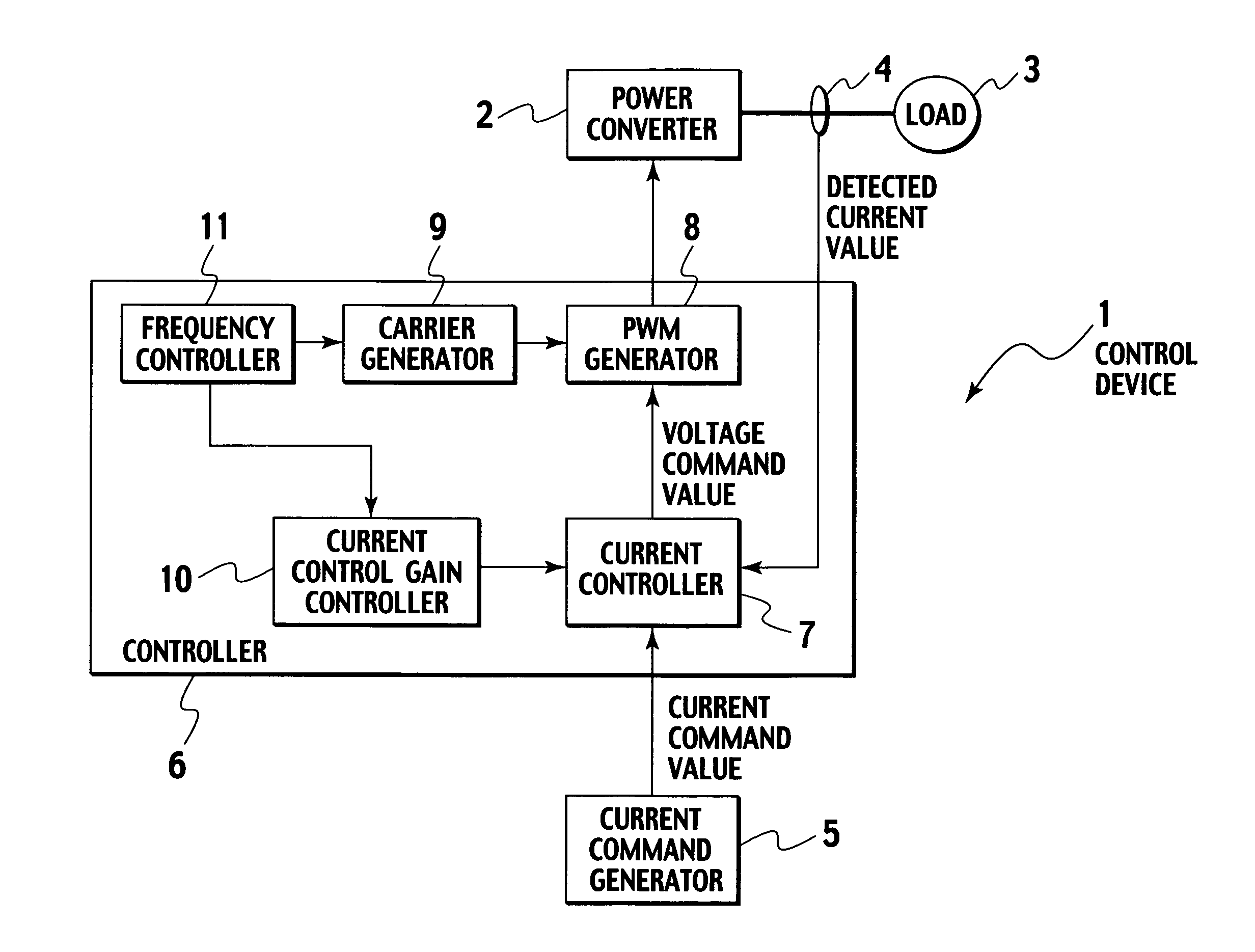
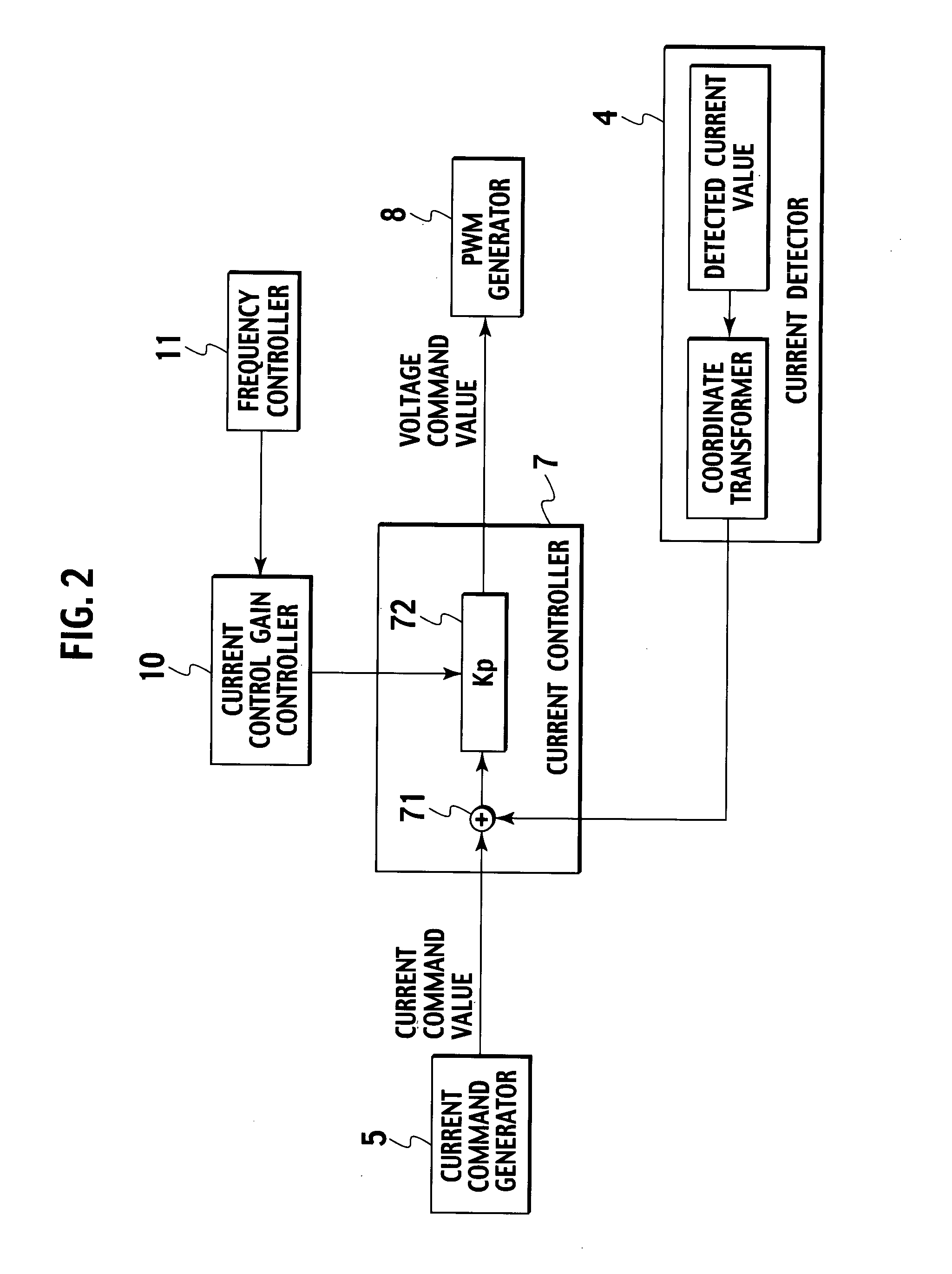
  • Claims
  • Application Information

AI Technical Summary

Benefits of technology

[0008] The present invention has been made in consideration for the above-described problems inherent in the related art. An object of the present invention is to provide a device and method for controlling a power converting device, which are designed to prevent the power converting device from impairing its control characteristics even when the power converting device effects a change in the frequency of a pulse width modulation carrier.
[0009] In order to solve the foregoing problems, the present invention provides a control device for a power converting device which performs pulse width modulation (PWM) on an output from a direct current power supply and thereby produces an output of alternating current power. The control device includes the followings: a current controller which converts a given current command value into a voltage command value; a carrier generator which generates a pulse width modulation (PWM) carrier; a PWM generator which generates a pulse width modulated (PWM) signal to be fed to the power converting device according to the voltage command value and the PWM carrier; a frequency controller which effects a change in the frequency of the PWM carrier from the carrier generator; and a current control gain controller which effects a change in the current control gain of the current controller according to the change in the frequency of the PWM carrier. In the control device, the current control gain of the current controller is changed according to the change in the frequency of the PWM carrier from the carrier generator. According to the present invention, the control device suppresses the occurrence of periodic variations due to the change in the PWM carrier frequency in an output current waveform from the power converting device, by effecting a change in the current control gain for conversion of the current command value to the voltage command value according to the change in the PWM carrier frequency. Thereby, the control device suppresses torque and other variations occurring in a load driven by the power converting device.
[0011] As for a transient response to the current command value, the control device includes a deviation detector which detects a deviation of an output current from the power converting device from the given current command value. Thus, the control device effects a change in the current control gain of the current controller according to the change in the PWM carrier frequency from the carrier generator, and also effects a change in the range of the current control gain according to the deviation. Thereby, the control device improves the transient characteristics of the output current waveform from the power converting device.

Problems solved by technology

This PWM-based controlling apparatus produces switching noise of a fundamental control frequency and higher harmonics thereof, because of doing switching to turn on or off a load driving current with a train of pulse width modulated pulses.
For example when the apparatus is mounted on a vehicle, the switching noise can possibly have an influence on hearing of a radio mounted on the identical vehicle and render it difficult to hear the radio or cause the radio to produce a harsh grating noise, or have an adverse effect on operation of other vehicle-mounted digital instruments.

Method used


Image

  • Device and method for controlling power converting device
  • Device and method for controlling power converting device
  • Device and method for controlling power converting device

Examples


first embodiment

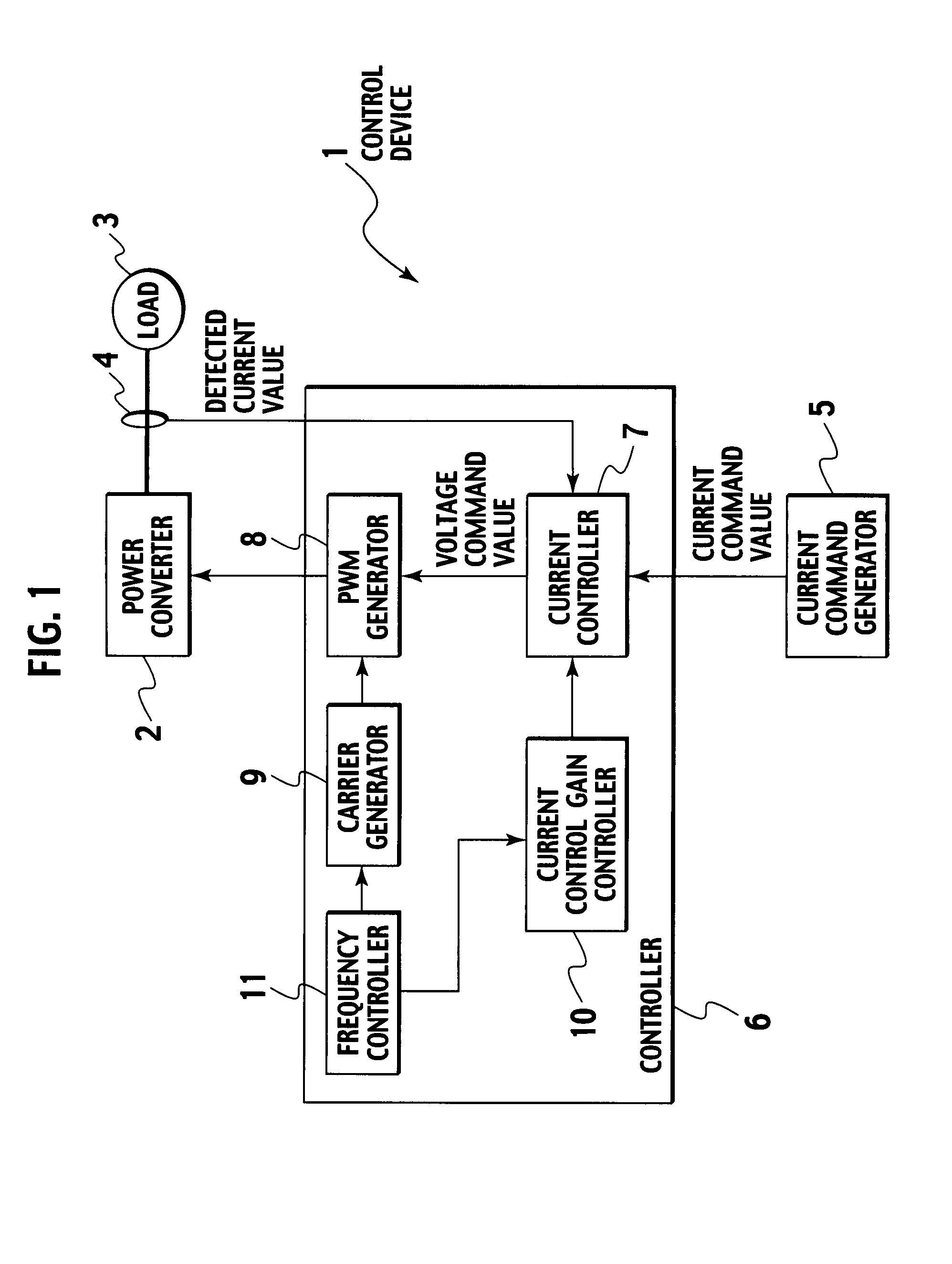
[0042]FIG. 1 is a block diagram showing an example of a power converting device and a device for controlling the same according to a first embodiment of the present invention.

[0043] Referring to FIG. 1, a power converter 2 is, for example, a PWM inverter, which is driven by a pulse width modulated signal (hereinafter referred to simply as a “PWM signal”) from a controller 6 to thereby supply alternating current power to a load 3 (e.g., a motor). A current detector 4 detects an alternating current flowing from the power converter 2 to the load 3 and sends the detected value to the controller 6. A current command generator 5 gives a command signal as to a current for driving the load 3. The current command generator 5 sends a current command value to the controller 6 according to the amount of accelerator operation or the like, for example when the power converting device is mounted on a vehicle.

[0044] The controller 6 is configured of a current controller 7, a PWM generator 8, a ca...

second embodiment

[0078]FIG. 12 is a block diagram showing a device for controlling a power converting device according to a second embodiment of the present invention.

[0079] The control device according to the second embodiment is provided with a map 12 that stores the correlation between a carrier frequency and a current control gain, in place of the frequency controller 11 shown in FIG. 1. A value read out from the map 12 is used to perform control in order for the carrier generator 9 to generate variable frequencies. In addition, a value from the map 12 is used to cause the current control gain controller 10 to change the current control gain of the current controller 7 according to a change in the carrier frequency. This makes it possible to effectively prevent the occurrence of a malfunction due to the change in the carrier frequency. The configuration of the other components is the same as that shown in FIG. 1 previously discussed.

[0080] As described above, the carrier frequency is mapped to...

third embodiment

[0081]FIG. 13 is a block diagram showing a device for controlling a power converting device according to a third embodiment of the present invention.

[0082] The control device according to the third embodiment is provided with a periodic frequency controller 13 that effects a periodic change in a frequency, in place of the frequency controller 11 shown in FIG. 1.

[0083] The periodic frequency controller 13 periodically modulates a carrier frequency to thereby facilitate calculating and estimating the carrier frequency. This enables changing a current control gain each time the carrier frequency changes, thus making it possible to effectively prevent the occurrence of a malfunction due to the carrier frequency.

[0084]FIG. 14 is a flowchart showing a method of controlling a current control gain according to the third embodiment.

[0085] The flowchart of FIG. 14 is formed of a combination of the flowcharts of FIGS. 5 and 6 previously discussed. Step S0″ of FIG. 14 involves executing ste...


PUM


Abstract

A control device for a power converting device which performs PWM on an output from a DC power supply and produces an output of AC power, including: a current controller which converts a given current command value into a voltage command value; a carrier generator which generates a PWM carrier; a PWM generator which generates a PWM signal to be fed to the power converting device according to the voltage command value and the PWM carrier; a frequency controller which effects a change in the frequency of the PWM carrier from the carrier generator; and a current control gain controller which effects a change in the current control gain of the current controller according to the change in the frequency of the PWM carrier. The current control gain of the current controller is changed according to the change in the frequency of the PWM carrier from the carrier generator.

Description

BACKGROUND OF THE INVENTION [0001] 1. Field of the Invention [0002] The present invention relates to a device and method for controlling a power converting device for performing pulse width modulation (PWM) on an output from a direct current (DC) power supply and thereby producing an output of alternating current (AC) power, and is concerned with a technique for preventing the occurrence of a malfunction due to a change in the frequency of a pulse width modulation carrier. [0003] 2. Description of the Related Art [0004] Apparatuses (such as a current control stepping motor) driven by a pulse width modulated signal are configured to control its operation by changing a duty ratio of a current waveform fed through the apparatus (or by performing pulse width modulation (hereinafter referred to simply as “PWM”)). This PWM-based controlling apparatus produces switching noise of a fundamental control frequency and higher harmonics thereof, because of doing switching to turn on or off a loa...

Claims


Application Information

Patent Timeline
IPC IPC(8): H02M1/12H02M7/48H02P21/00H02P21/05H02P21/22H02P23/04H02P23/07H02P27/08
CPCH02M7/53875H02P21/0096H02P21/00H02M2003/1555H02P21/50H02M3/1555
Inventor SHIN, KENTAROUHAYAMI, YASUAKITHRONGNUMCHAI, KRAISORNKAI, TOSHIHIRO
Owner NISSAN MOTOR CO LTD
Learn More