Driving device, driving mechanism, and image sensing apparatus

a driving mechanism and driving device technology, applied in the direction of instruments, printers, cameras, etc., can solve the problems of reducing the size and weight of the lens driving mechanism, lowering the impact resistance, etc., and achieve the effect of reducing the size and weight of the driving device and reducing the displacement amoun

Inactive Publication Date: 2007-12-06
KONICA MINOLTA OPTO
View PDF4 Cites 95 Cited by
  • Summary
  • Abstract
  • Description
  • Claims
  • Application Information

AI Technical Summary

Benefits of technology

[0010] In view of the above problems residing in the prior art, it is an object of the invention to provide a driving device with an SMA actuator, which enables to obtain a large...

Problems solved by technology

This may increase an inertia moment of the lens frame member when an impact is applied thereto, thereby lowering the impact resist...

Method used


Image

  • Driving device, driving mechanism, and image sensing apparatus
  • Driving device, driving mechanism, and image sensing apparatus
  • Driving device, driving mechanism, and image sensing apparatus

Examples


first embodiment

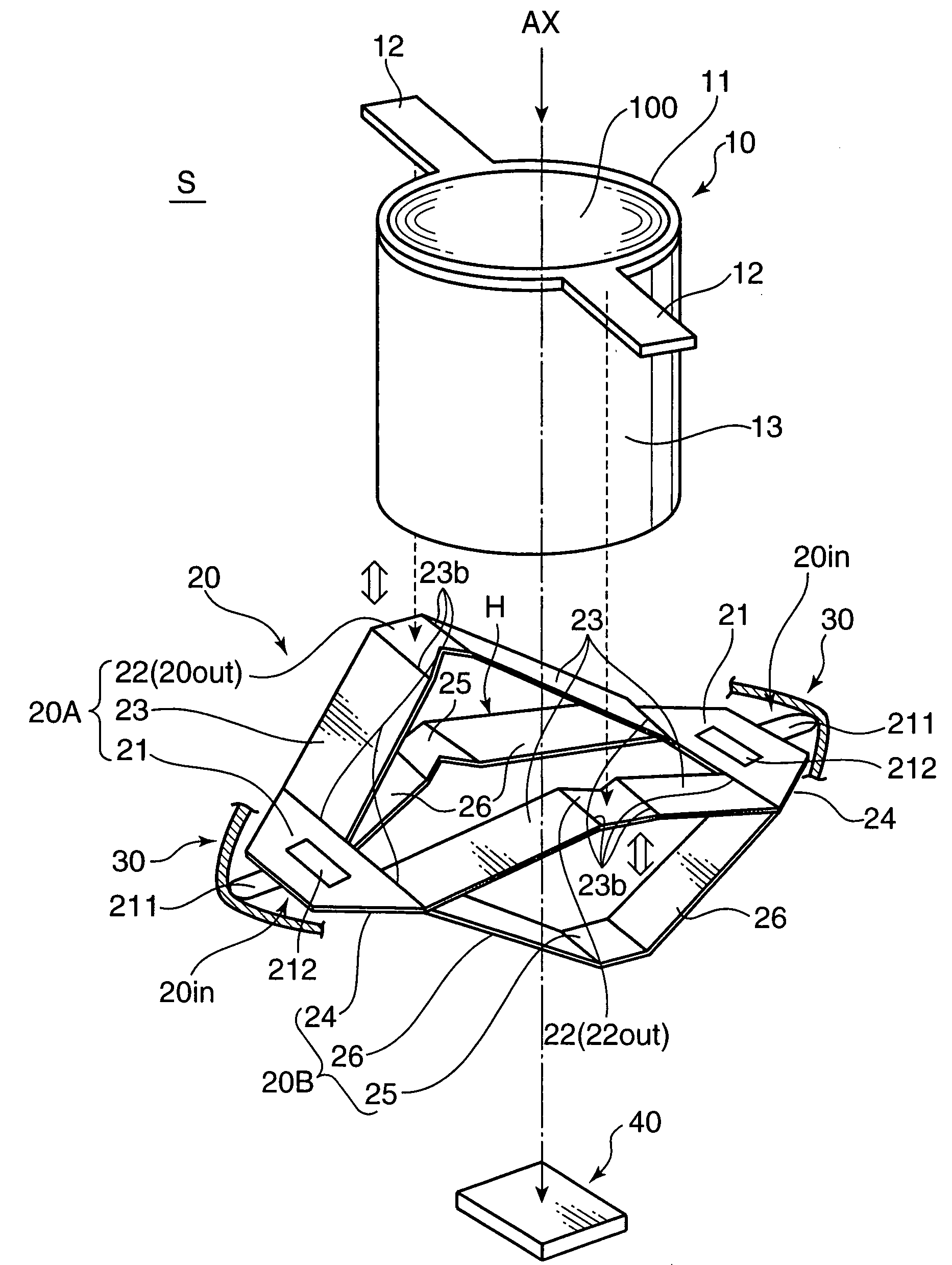
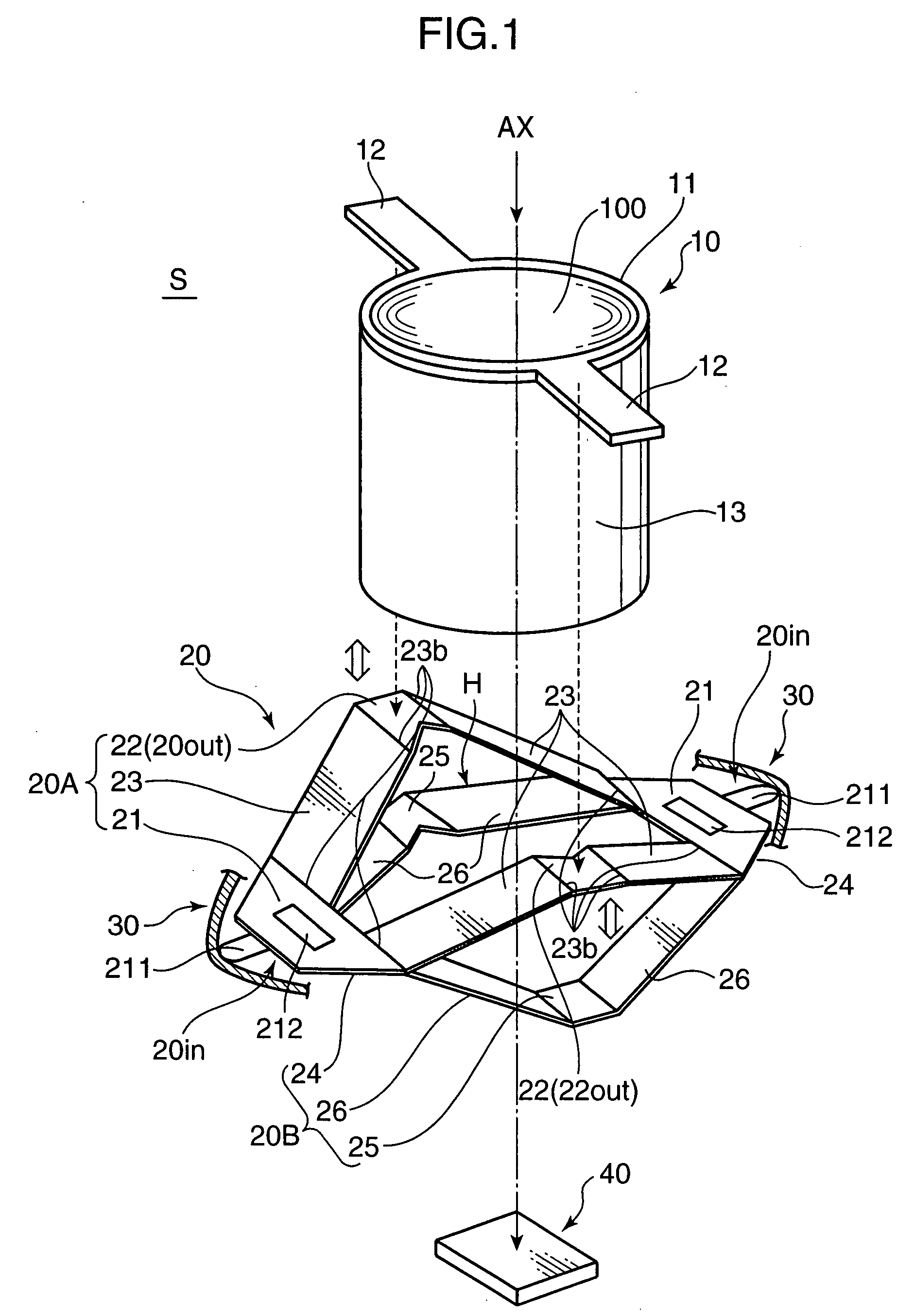
[0056]FIG. 1 is an exploded perspective view showing primary components of a lens driving module S i.e. an image sensing apparatus including a lens driving mechanism as a first embodiment. The lens driving module S primarily include a lens unit 10 as a driven member, a driving member 20 for moving the lens unit 10 in an optical axis AX direction i.e. a first axis direction, and an SMA actuator 30. An image sensor 40 for photoelectrically converting a subject light image into electrical signals is provided on the imaging side of the lens unit 10.

[0057] The lens unit 10 has a cylindrical shape, and includes a taking lens portion 100, a lens driving frame 11 for holding the taking lens portion 100, and a lens barrel 13 for housing the lens driving frame 11. The taking lens portion 100 has an objective lens, a focus lens, and a zoom lens, and constitutes an imaging optical system for imaging a subject image by the image sensor 40. The lens driving frame 11 is a so-called lens frame mem...

second embodiment

[0179] In this section, a second embodiment using two flat plate members is described. FIG. 29 is a side view showing a driving module S1 to which a driving mechanism of the second embodiment is applied. The driving module S1 includes a driven member 14, and a driving device 400 for driving the driven member 14 in the Z-axis direction as the first axis direction.

[0180] The driving device 400 has a driving member and an SMA actuator 430. In the second embodiment, the driving member is constituted of a flat plate unit 41 i.e. a first flat plate member 41A and a second flat plate member 41B, two spacers 42 as a gap holder, and a gap increasing member 43. FIG. 29 shows a state that the SMA actuator 430 is not operated i.e. not contracted.

[0181] The two flat plate members 41A and 41B each is made of a metal or a resin having elasticity, and is a thin plate with a rectangular shape in plan view, on which a specific process such as a bending process is not applied. The first flat plate m...


PUM


Abstract

A driving device is adapted to drive a driven member, and includes a driving member, and a linear shape memory alloy (SMA) actuator. The driving member has a displacement output portion which is movable in a first axis direction, and a displacement input portion for moving the displacement output portion in the first axis direction in response to an application of a moving force in a second axis direction orthogonal to the first axis direction. The driving member is engaged with the driven member at the displacement output portion. The SMA actuator is disposed in contact with the driving member at least at the displacement input portion to apply the moving force to the displacement input portion.

Description

[0001] This application is based on Japanese Patent Application Nos. 2006-149935, 2006-194199, 2006-194200, and 2007-063684 filed on May 30, 2006, Jul. 14, 2006, Jul. 14, 2006, and Mar. 13, 2007, respectively, the contents of which are hereby incorporated by reference. BACKGROUND OF THE INVENTION [0002] 1. Field of the Invention [0003] The present invention relates to a driving device for driving a lens unit constituting an imaging optical system of an image sensing apparatus such as a camera phone for zoom control or focus control, as well as a driving mechanism, and an image sensing apparatus incorporated with the driving device. [0004] 2. Description of the Background Art [0005] In recent years, a high-quality camera phone or a like device has been developed. For instance, the number of pixels of an image sensor to be loaded in a camera phone has been spectacularly increased. As the high-quality camera phone has been developed, a high-performance lens unit constituting an imaging...

Claims


Application Information

Patent Timeline
IPC IPC(8): G03B3/10
CPCG03B3/10G02B7/04F03G7/065
Inventor KUBO, NAOKITANII, JUNICHIWADA, SHIGERU
Owner KONICA MINOLTA OPTO
Why Eureka
Try Eureka