Multi-joint fixture system

a fixture system and joint technology, applied in the field of multi-joint fixture system, can solve the problems of increasing the risk of the instrument being held with less strength and/or precision than is desirable, the fixture is manual intensive and cumbersome, and the practitioner is fatigued, etc., to achieve the effect of increasing the level of force, reducing the risk of the instrument being held with less strength and/or precision, and high degree of positional flexibility and ease of us

Inactive Publication Date: 2007-12-06
SURGICAL CONCEPT DESIGNS
View PDF19 Cites 38 Cited by
  • Summary
  • Abstract
  • Description
  • Claims
  • Application Information

AI Technical Summary

Benefits of technology

[0008]Advantageously, such embodiments provide for a fixture having a high degree of positional flexibility and ease-of-use. More particularly, the plurality of arms and the plurality of ball joints provides for a fixture that can place a surgical instrument in a given position with a variety of different configurations, thereby avoiding configurations that would obstruct a medical practitioner's work. Moreover, the electromagnetic brakes provide for a fixture configuration that is strong, and yet can be locked and unlocked rapidly with the press of a single button.
[0009]The invention may further provide for lever arms that leverage the force of the electromagnetic actuators to increased levels of force. Such lever arms advantageously allow the use of electromagnets that consume less power and are smaller, lighter in weight and less expensive.
[0010]The invention may further provide the fixture with ball joint centering mechanisms that bias ball joint positions toward a single, neutral (center) position. Such centering mechanisms typically provide the fixture with a single, predictable configuration (or limited number of configurations) having a minimum potential energy for most any position of the surgical instrument. Moreover, the invention may further provide for a level of joint rigid

Problems solved by technology

Frequently, the instruments must be held for extended periods of time, causing fatigue in the practitioner holding the instrument, and increasing their risk of the instrument being held with less strength and/or precision than is desirable.
Such fixtures tend to be manually intensive and cumbersome, requiring significant labor to position and lock in place.
Additionally, many of these fixtures have limited range of motion, of

Method used


Image

  • Multi-joint fixture system
  • Multi-joint fixture system
  • Multi-joint fixture system

Examples


first embodiment

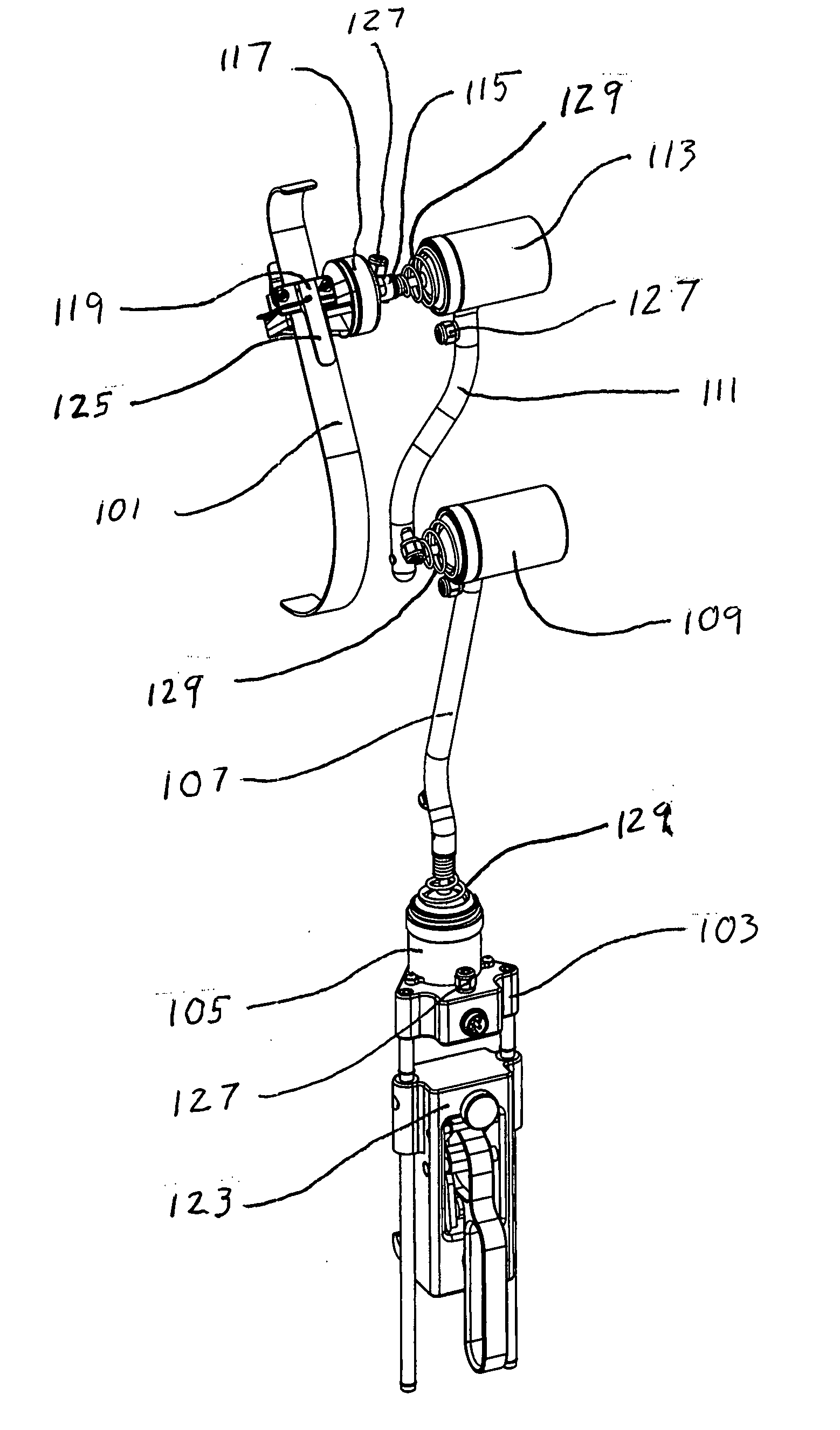
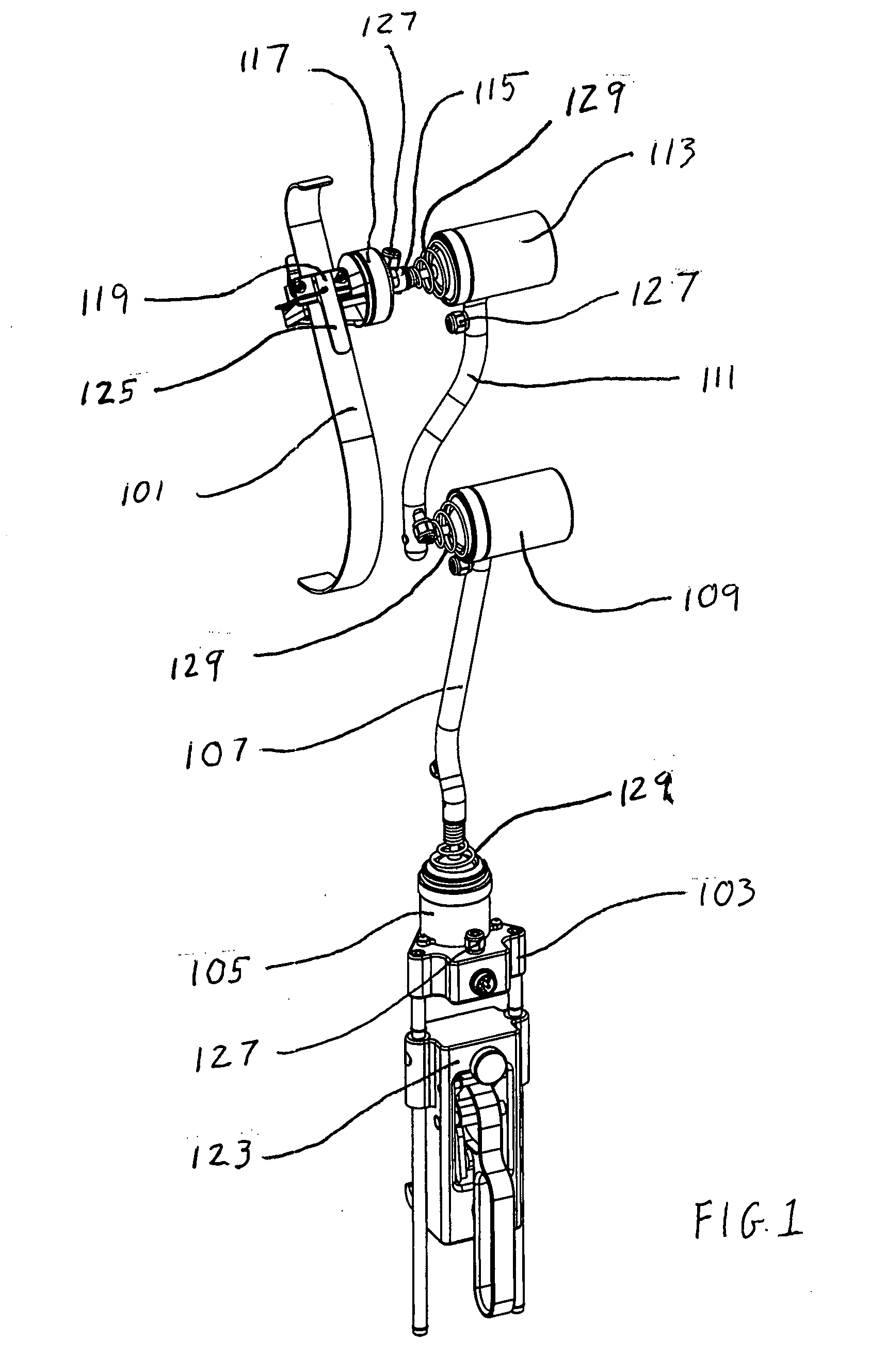
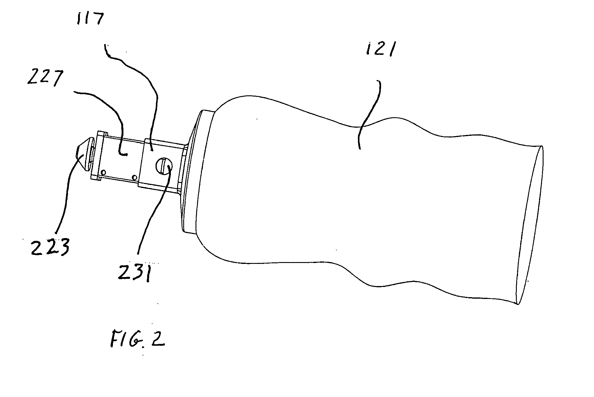
[0031]With reference to FIG. 1, the invention forms a multi-joint fixture for holding a surgical instrument 101 such as a surgical retractor (shown), an endoscope, a limb positioner, or the like. In this context, the term instrument should be understood to include any useful object that a medical practitioner might wish to be held stationary during surgery.

[0032]The fixture includes a base unit 103, a first joint 105, a first arm 107, a second joint 109, a second arm 111, a third joint 113 and a fixture hub 115. The first joint adjustably connects a proximal end of the first arm to the base unit, the second joint adjustably connects a proximal end of the second arm to a distal end of the first arm, and the third joint adjustably connects the fixture hub to a distal end of the second arm. The fixture thus includes a plurality of three joints interconnecting a plurality of four members (including the two arms), each joint having an attached member to which it is rigidly attached and a...

second embodiment

[0094]The offset ball joint of this second embodiment is of an offset configuration in that its actuation elements (e.g., an electromagnet, and a draw-plate that establishes a closable gap with the electromagnet) and its braking elements (e.g., a plurality of hardened ring brake elements on opposing sides of the ball) extend and act along two separate, offset and parallel longitudinal axes. It is also of a levered configuration, in that the lever arm provides a four to one mechanical advantage, allowing for a smaller electromagnet to be used.

[0095]If the primary housing is rigidly attached to (or unitary with) an arm, the offset configuration of this joint provides a simple way for the masses of the housing, the electromagnetic brake mechanism (e.g., the electromagnet and draw-plate), and the spherical portion of the ball to all be placed substantially along a longitudinal arm axis (i.e., an axis generally defined by the extent of the arm from its proximal to its distal end), while ...

third embodiment

[0103]This third embodiment is an example of a fixture characterized by a failsafe locked configuration, and uses joints that lack a levered configuration to leverage the applied braking force to a higher value than that actually generated by their magnets. Other failsafe, locked joint configurations, such as offset configurations and / or levered configurations are also envisioned.

[0104]While the first and third and embodiments were described as fixtures having a single type of ball joint, the second embodiment was described as having a first ball joint in a linear, levered, failsafe unlocked configuration, and a second and third ball joint in an offset, levered, failsafe unlocked configuration. Embodiments having other combinations of ball joints are also envisioned. For example, it is envisioned that a multi-joint fixture could have a first ball joint characterized by a failsafe locked configuration, and second and third ball joints characterized by a failsafe unlocked configuratio...


PUM


Abstract

A multi-joint fixture including a proximal base unit, one or more arms serially connected by electromagnetically lockable ball joints, and a distal hub. The ball joints unlock when not powered. A centering mechanism biases the ball joints toward a neutral position. A control system activates the electromagnetic brake with a high-then-low voltage profile. A headpiece attaches to the hub and holds a drape that covers the fixture. A connector connects a surgical device to the headpiece. A switch on the hub can be actuated via actuators on the headpiece or connector.

Description

[0001]This application claims the benefit of U.S. provisional Application No. 60 / 810,265, filed Jun. 1, 2006, which is incorporated herein by reference for all purposes.[0002]The present invention relates generally to an arm-like fixture for positioning objects such as surgical instruments, and more particularly, to a multi-joint fixture for holding such objects, the fixture having arm segments connected with lockable ball joints.BACKGROUND OF THE INVENTION[0003]There is a need during various surgical procedures for instruments such as retractors to be held for extended periods of time in stationary positions. Typically, such holding is done by a medical practitioner, such as a surgical assistant, under the direction of a doctor. In some cases, the instruments must be held with some degree of strength, and / or with a great deal of precision. Frequently, the instruments must be held for extended periods of time, causing fatigue in the practitioner holding the instrument, and increasin...

Claims


Application Information

Patent Timeline
IPC IPC(8): A61B17/00A61B46/23
CPCA61B17/02Y10T403/32311A61B19/081A61B19/22A61B19/26A61B2019/0249A61B2019/025A61B19/0256A61B19/10F16C11/06F16C11/10F16D63/002F16M13/022A61B2017/00398A61B2017/00876A61B2019/266A61B19/0248A61B34/70A61B46/10A61B50/10A61B50/13A61B90/50A61B2050/105A61B2090/508A61B46/23A61B50/20
Inventor SCOTT, CHRISTOPHER P.LAGANIS, EDWARD J.LA ROSA, ANTHONY J.CAHAYLA, JASON ROBERT
Owner SURGICAL CONCEPT DESIGNS
Why Eureka
Try Eureka