Cavity creation device and methods of use

a cavity creation and cavity technology, applied in the field of medical devices and components, can solve the problems of shortening and tilting of the spinal column with a forward curvature, pulmonary and gastrointestinal complications, fractures are extremely painful and debilitating, etc., to achieve accurate, rapid and safe placement, and reduce radiation exposure. , the effect of accurate alignment of the bone drill

Inactive Publication Date: 2007-12-06
OSTEO INNOVATIONS
View PDF15 Cites 37 Cited by
  • Summary
  • Abstract
  • Description
  • Claims
  • Application Information

AI Technical Summary

Benefits of technology

[0014]An off-angle, largely translucent bone access drill having a cavity drill is provided for placing in one step an access needle/tube/conduit into targeted bone. The drill also has radio opaque markers allowing more accurate alignment of the bone drill during use under fluoroscopic guidance. These attributes allow more accurate, rapid, and safe placement of the access needle/tube/conduit into the targeted bone. The present disclosure also reduces radiation exposure to the physician by

Problems solved by technology

Osteoporosis is the most common cause for vertebral compression fractures and sacral fractures, however, bone tumors involving the spine such as multiple myeloma and metastatic disease can also cause these fractures.
This can lead to shortening and tilting of the spinal column with a forward curvature.
This forward curvature can lead to pulmonary and gastrointestinal complications.
These fractures are extremely painful and debilitating with many of these patients needing wheelchairs for less painful ambulation; many of these patients are bed-ridden.
However, existing drills suffer from various design defects that make them unsuitable to be used with fluoroscopic (X-ray) or computed tomographic (CT) guidance for these procedures.
It is often difficult to place needles

Method used


Image

  • Cavity creation device and methods of use
  • Cavity creation device and methods of use
  • Cavity creation device and methods of use

Examples


Embodiment Construction

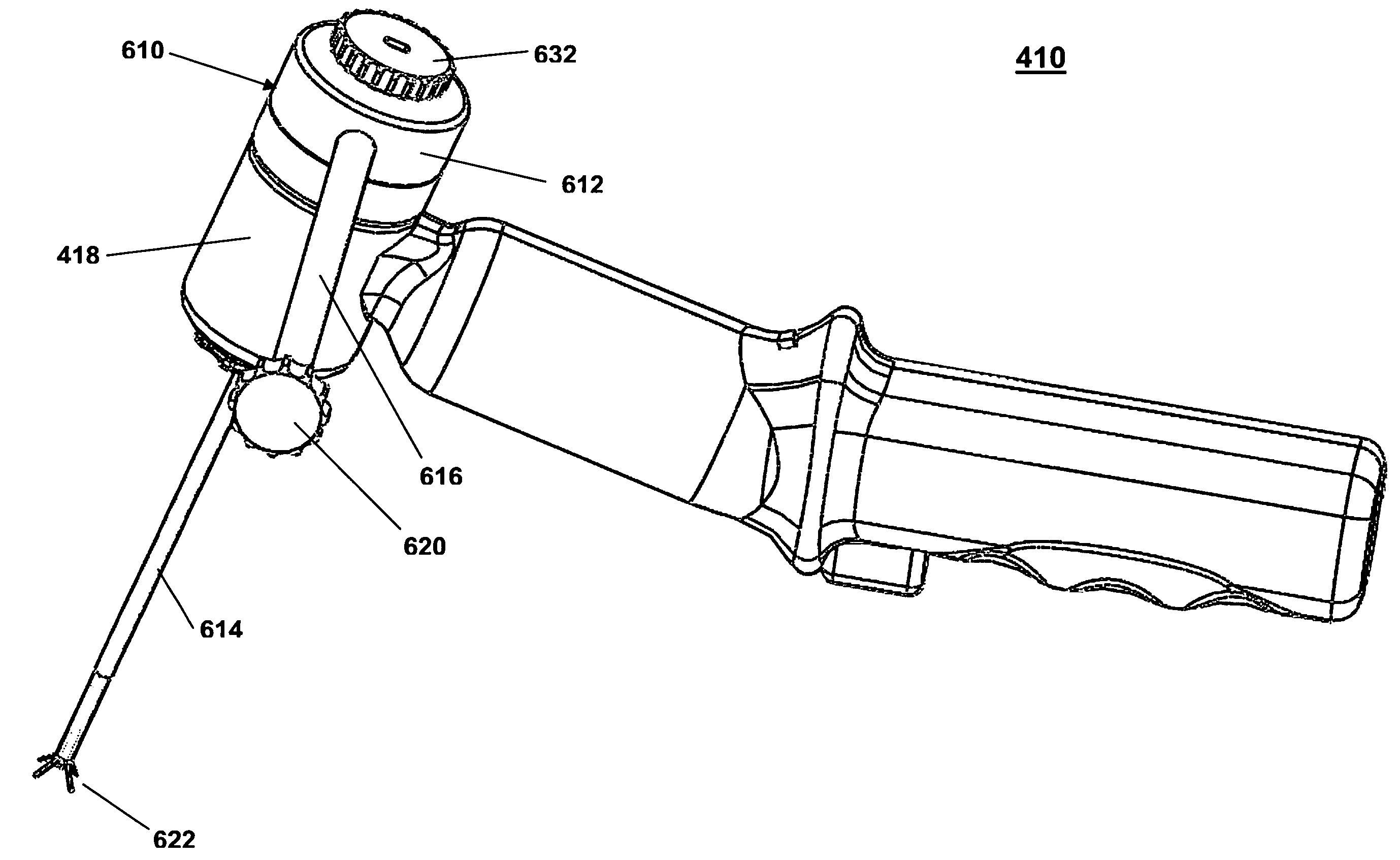
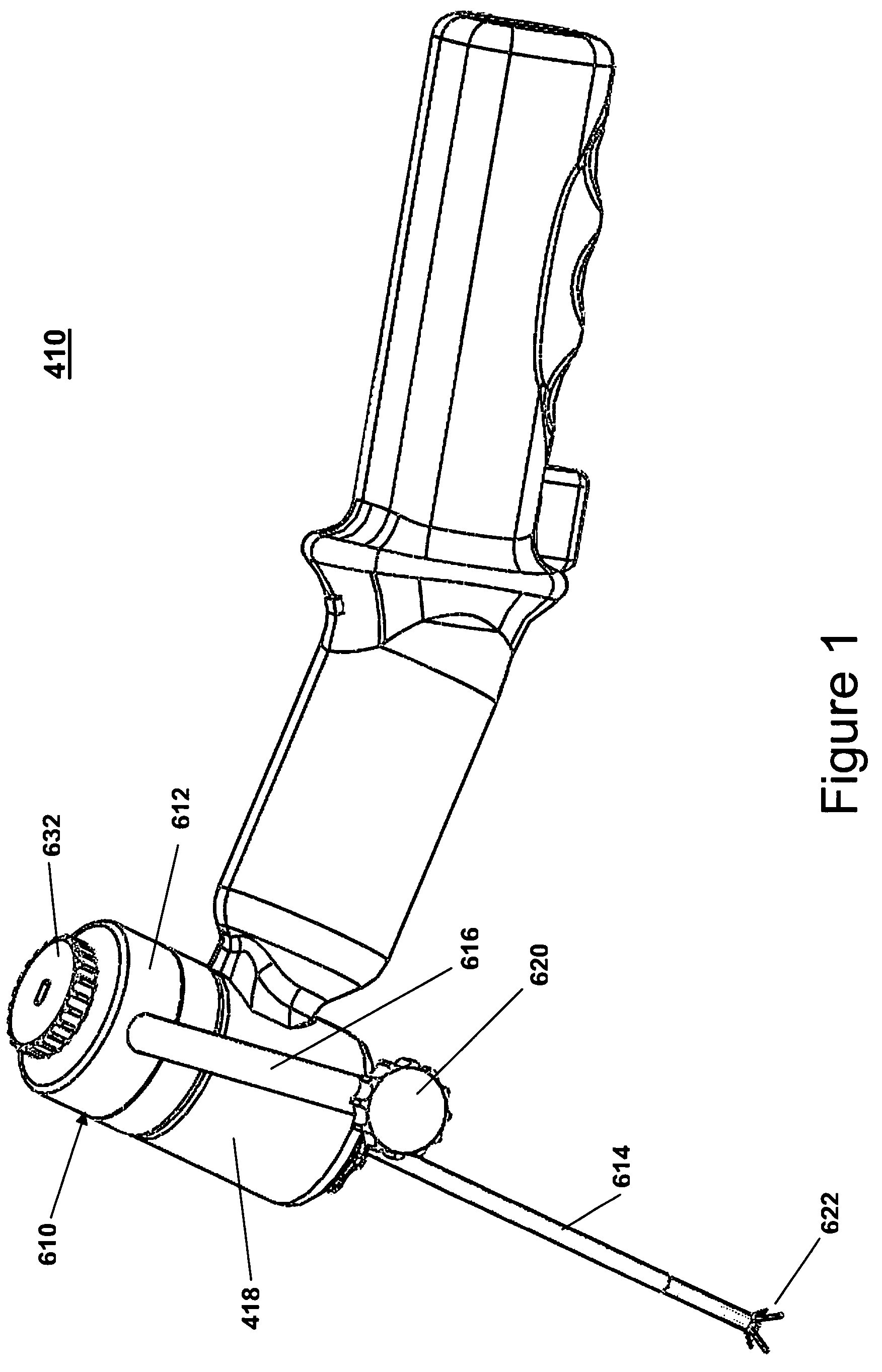
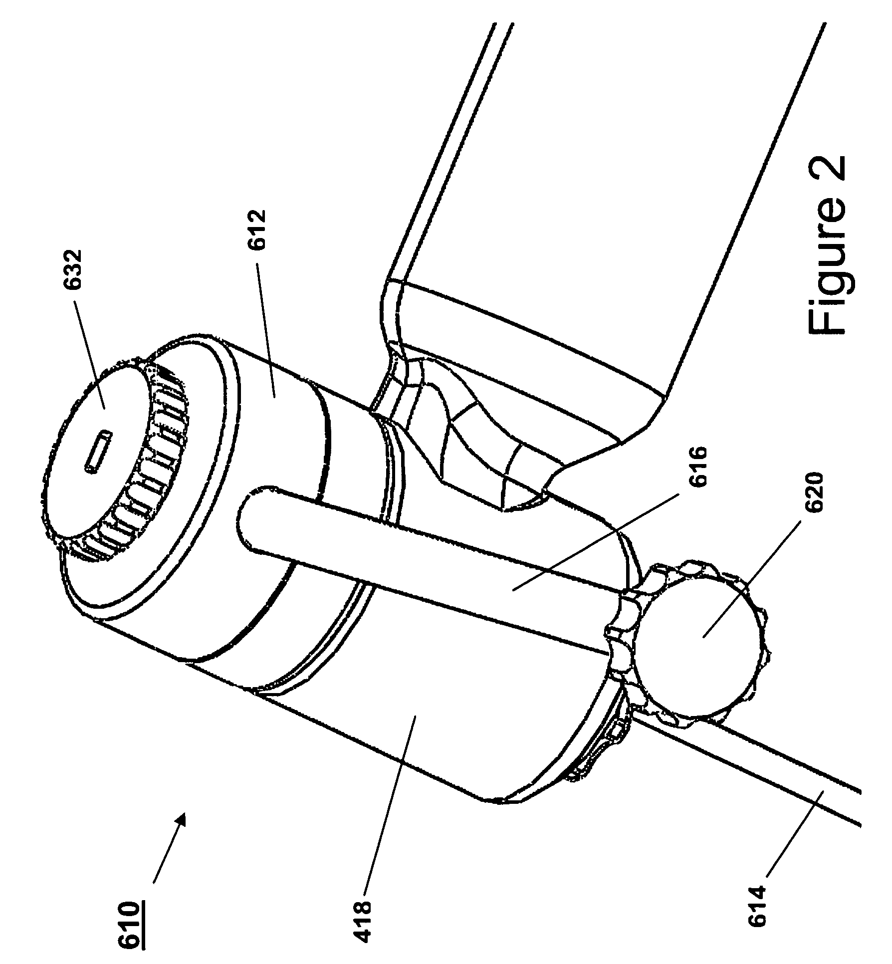
[0059]The exemplary embodiments of the bone drill and methods of use disclosed are discussed in terms of medical apparatus and more particularly, in terms of bone drills, bone drill assemblies and bone cavity drills that can be employed for treating vertebral body and sacral fractures. The bone drill may also be employed to treat lytic tumor deposits in bone. It is envisioned that the present disclosure may be employed with a range of applications including vertebroplasty and / or vertebral augmentation procedures, sacroplasty and osteoplasty. The bone curette is designed with snapping features to lock and release from the bone drill; the bone drill turns / powers the curette blades. The curette blades may have radio opaque markers to increase conspicuity. The curette can be used to create a cavity inside a bone for various medical applications and treatment procedures. It is envisioned that the present disclosure may be used to provide access for bone biopsies and bone infusions. It is...


PUM


Abstract

A cavity drill is provided, which is configured for use with a bone drill. The cavity drill includes a body. The bone drill has a first portion movably connected to a second portion. A third portion is movably connected to the second portion. The body is mounted with the third portion of the bone drill. A sheath extends from the third portion to a distal end. A curette is connected with the distal end of the bone drill. The curette is composed of retractable cutting tines/blades which are turned/powered by the bone drill motor. The curette tines can be used in a partially or fully deployed state and at low or high speed. The curette is designed to create cavities of varying size in a bone. The cavity drill and the bone drill may include a radiation protection guard and radiolucent portions. Methods of use are also provided.

Description

CROSS REFERENCE TO RELATED APPLICATIONS[0001]This patent application claims the benefit of U.S. Provisional Patent Application Ser. No. 60 / 809,945, filed on Jun. 1, 2006, the contents of which being incorporated herein by reference in its entirety.I. BACKGROUND OF THE INVENTION[0002]A. Field of the Invention[0003]The present disclosure relates to medical devices, components, and methods for use thereof, such as bone drills, bone drill assemblies, bone impact drills, bone cavity creation / enlargement devices, guide forceps, and fluid transfer devices especially those for treating vertebral body and sacral fractures, as well as lytic (destructive) tumor deposits in bone, for use in bone biopsies / bone infusions, for procedures requiring bone access and for use in medical procedures requiring a drill driven screwdriver or similar tools especially when there is a need for an off-angle, largely translucent bone access device having radiation protection for the operator designed to be used ...

Claims


Application Information

Patent Timeline
IPC IPC(8): A61B17/16
CPCA61B17/1615A61B19/54A61B17/1671A61B17/1624A61B90/39
Inventor YEDLICKA, JOSEPH W.TILL, ROBERT A.YEDLICKA, NANCY S.TILL, PATRICIA M.
Owner OSTEO INNOVATIONS
Why Eureka
Try Eureka