Composite trigger for a digital sampling oscilloscope

a digital sampling and trigger technology, applied in the direction of mechanical measurement arrangements, mechanical roughness/irregularity measurements, instruments, etc., can solve the problems of inability to produce a hundred or more volts peak to peak at several gigahertz at the vertical deflection plate of a crt, and the component path of an analog component is difficult to achiev

Inactive Publication Date: 2007-12-06
AGILENT TECH INC
View PDF1 Cites 54 Cited by
  • Summary
  • Abstract
  • Description
  • Claims
  • Application Information

AI Technical Summary

Problems solved by technology

It turns out that to get all the components in the vertical path of an analog 'scope to perform at high bandwidths is a significant engineering challenge.
DC coupled amplifiers that will produce a hundred or more volts peak to peak at several gigahertz at a CRT's vertical deflection plates are not practical, not to mention that the writing rate for a normal CRT does not go that high.
The underlying technical issue here is that it is far easier to design and build high speed samplers and ADCs (Analog to Digital Converters) and fashion a high speed path into memory (say, by interleaving many banks of memory) than it is to design and build the equivalent actual analog signal path (amplifiers and CRT).
But if the Acquisition Record has several million (or several tens of millions) of addressable locations, then there arises the issue of how to decide what image to store in the Frame Buffer.
On the o...

Method used


Image

  • Composite trigger for a digital sampling oscilloscope
  • Composite trigger for a digital sampling oscilloscope
  • Composite trigger for a digital sampling oscilloscope

Examples


Embodiment Construction

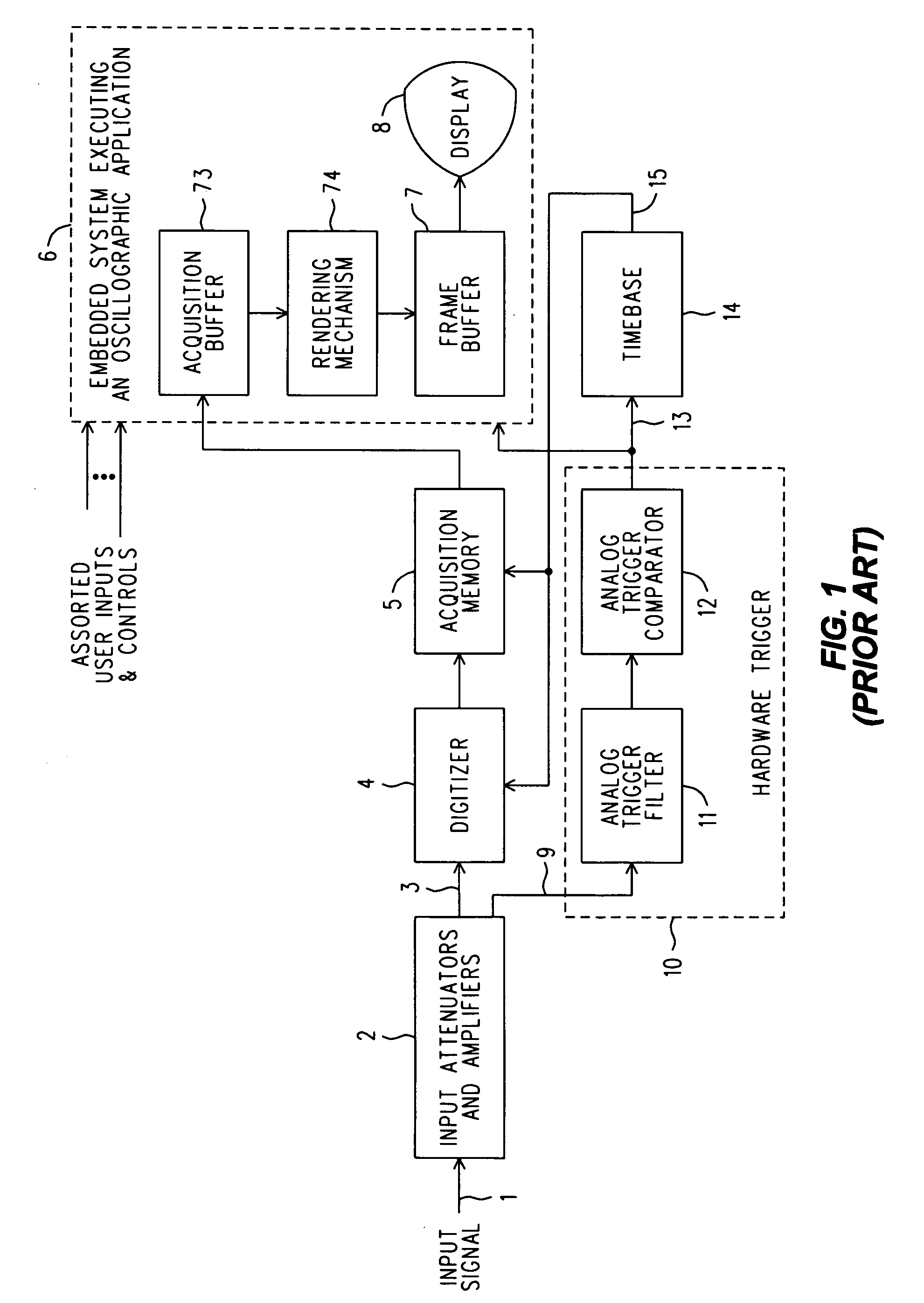
[0030]Refer now to FIG. 1, wherein is shown a simplified block diagram of a prior art DSO architecture that uses a conventional Hardware Trigger (10), and that may be taken as a point of departure for the implementation of a Composite Trigger that includes a S / W Trigger component. In particular, an Input Signal 1 in applied to various Input Attenuators and Amplifiers 2, where signal conditioning takes place. A Conditioned Input Signal 3, which will be a suitable replica of the Actual Input Signal 1, is applied to a Digitizer (or ADC—Analog to Digital Converter) 4 whose output is a series of digital words (preferably integers) of a suitable number of bits, say eight or ten, depending upon the vertical resolution the DSO is to have. The series of digital words is applied to an Acquisition Memory 5 that stores them internally as an Acquisition Record (a data structure, and not itself shown). To free the Acquisition Memory to begin as soon as possible to begin acquiring another Acquisit...


PUM


Abstract

A Composite Trigger for a DSO provisionally honors a conventional hardware trigger by algorithmically investigating the content of the associated Acquisition Record for a selected signal attribute (a S/W Trigger). If found, the hardware trigger is fully honored by displaying the Acquisition Record with a previously selected time scale and with the time reference set to where in the trace the selected signal attribute occurs. The selected attribute may include the occurrence of a stated value or stated range of values for any automatic measurement upon a trace that the 'scope is otherwise equipped to perform. In addition to being based on existing automatic measurements, the Composite Trigger can also be satisfied whenever subsequent investigation determines that a segment of trace described by the Acquisition Record does or does not pass through one or more zones defined relative to an existing time reference. The Composite Trigger can also be based on whether a trace can be interpreted as exhibiting a selected serial bit pattern, or, upon whether the trace represents an edge that is not monotonic.

Description

INTRODUCTION AND BACKGROUND[0001]An oscilloscope needs a way to make consecutive segments of a repetitive waveform ‘stand still’ when displayed. In the old days of uncalibrated horizontal sweep speeds this was done by varying the frequency of the sawtooth waveform that provided the horizontal sweep, until synchronism produced a stable display. Typically, some variable amount of the vertical input signal was coupled into the sweep oscillator to ‘encourage’ it to remain synchronized (as through a rudimentary sort of phase locking). Later, when analog 'scopes were equipped with calibrated sweep speeds, synchronization was obtained by triggering individual cycles of the sweep oscillator by a threshold detector driven by a conditioned version of the vertical input signal. This manner of triggering has survived, and even today's Digital Sampling Oscilloscopes (DSOs) use a refined version of this, which technique we shall term a ‘hardware trigger’ (H / W Trigger).[0002]High performance analo...

Claims


Application Information

Patent Timeline
IPC IPC(8): G01B5/28G01B5/30G06F19/00
CPCG01R13/0254
Inventor DUFF, CHRISTOPHER P.GENTHER, SCOTT ALLAN
Owner AGILENT TECH INC
Why Eureka
Try Eureka