Eureka AIR delivers breakthrough ideas for toughest innovation challenges, trusted by R&D personnel around the world.

Waveform three-dimensional imaging method

A three-dimensional imaging and three-dimensional technology, applied in the direction of digital variable/waveform display, measuring device, instrument, etc., can solve the problems of occasional signals that are difficult to identify, information loss, low repetition signal and random signal capture ability, etc., to improve the capture ability , to avoid the effect of information loss

Inactive Publication Date: 2013-09-04
UNIV OF ELECTRONIC SCI & TECH OF CHINA
View PDF4 Cites 18 Cited by
  • Summary
  • Abstract
  • Description
  • Claims
  • Application Information

AI Technical Summary

Problems solved by technology

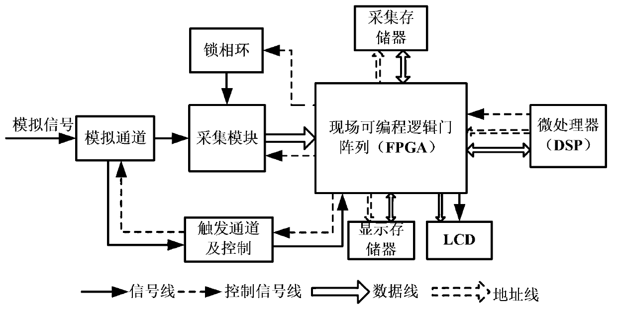
For example, the maximum real-time sampling rate of a digital oscilloscope is 6GSPS, the maximum storage depth is 300Kpts, the resolution of the LCD display is 320×240, the actual waveform display area is 300×200, the time base is 1us / div, and the oscilloscope display is 10 grids, then 300K sampling points will be collected once triggered, but only 300 points can be displayed on the LCD, so 300 points must be extracted from 300K sampling points for display
The sampling process will inevitably lose the data of accidental events, thereby reducing the accuracy of analyzing accidental events
In addition, the monochrome display of the waveform makes infrequent signals difficult to read even when special events are extracted by sampling
It can be seen that the information lost in the sampling processing in the traditional digital storage oscilloscope makes the acquisition system less capable of capturing low repetitive signals and random signals

Method used


Image

  • Waveform three-dimensional imaging method
  • Waveform three-dimensional imaging method
  • Waveform three-dimensional imaging method

Examples


Embodiment

[0048] In this embodiment, a dual-channel data storage oscilloscope is used for simulation, the simulation bandwidth is 100MHz, the actual sampling rate is 2GSPS, the maximum storage depth is 25K, and the LCD resolution is 300×200, that is, the number of horizontal display points S=300, and the time base of the oscilloscope is set It is 100us / div; the selected signal source is SP1461 digital high-frequency signal generator, and the signal source is a sine amplitude modulation wave with a carrier frequency of 435kHz, a modulating wave frequency of 1kHz, and a modulation degree of 50%. The software compiler is VisualDSP++5.0.

[0049] Figure 5 It is a figure for three-dimensional display of sinusoidal modulation wave by adopting the present invention. Such as Figure 5 As shown in the figure, under single acquisition, the waveform is fully displayed in the way of "time compression". In this embodiment, the stretch-to-width ratio adopts the default value, that is, M=1, and at...


PUM


Abstract

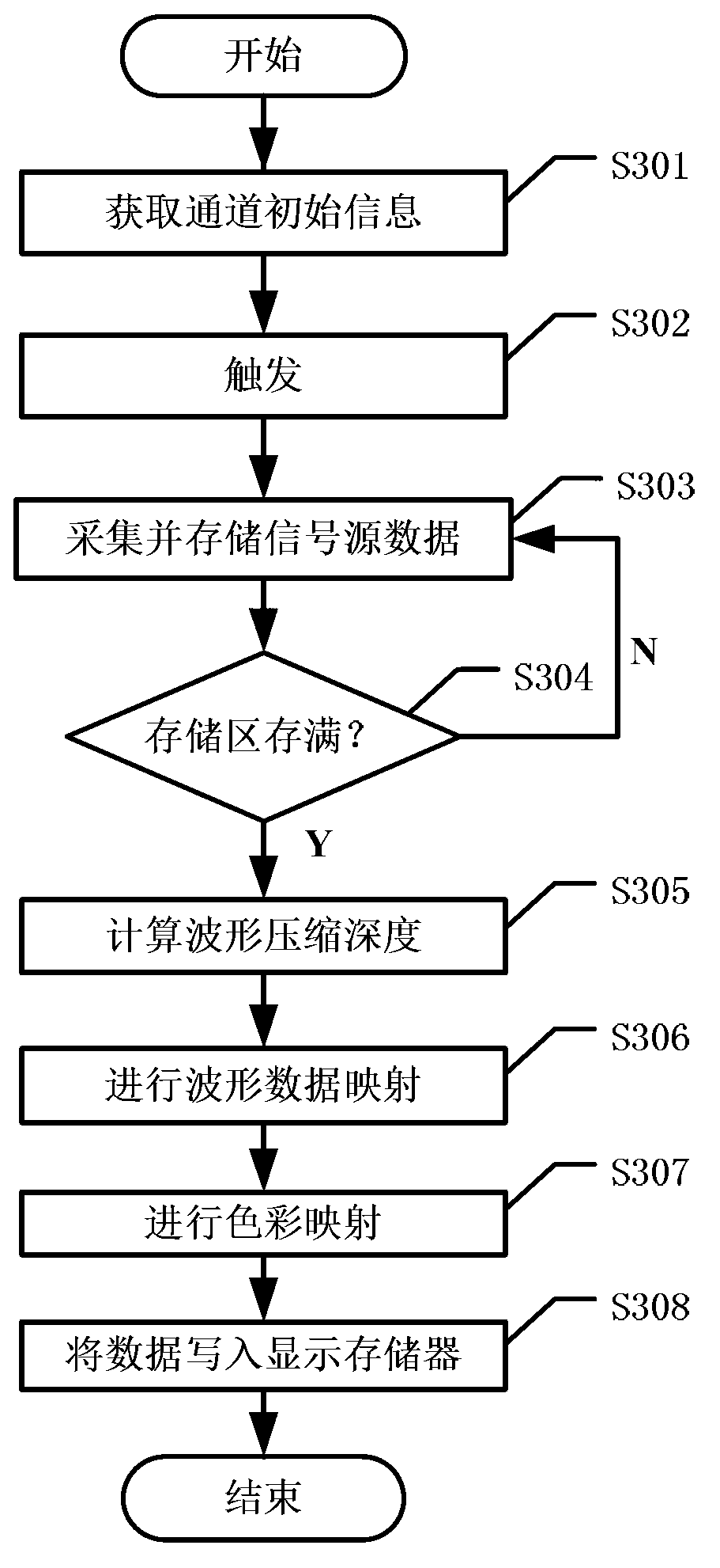
The invention discloses a waveform three-dimensional imaging method. The compression depth H is obtained according to the horizontally compressed waveform length obtained through the set widening ratio, every H sampling points are compressed on one time point, and the occurrence number of the amplitude value of the H sampling points on the time point is superposed, so the probability that the H sampling points are in different amplitude values on the time point is obtained, and the time-amplitude two-dimension sampling information is mapped into time-amplitude-amplitude occurrence probability three-dimensional data, wherein the color shades is adopted for representing the amplitude occurrence probability value. When the waveform three-dimensional imaging method is adopted, the waveform three-dimensional imaging can be realized in the traditional serial architecture DSO (digital storage oscilloscope), the information loss caused by snapshot sampling processing is avoided, and the trapping capacity of low repeated signals and random signals is improved.

Description

technical field [0001] The invention belongs to the technical field of oscilloscope waveform imaging, and more specifically relates to a waveform three-dimensional imaging method. Background technique [0002] The increase of signal bandwidth and non-stationary characteristics makes it difficult for traditional frequency domain testing to meet the requirements of high-speed and seamless testing of bandwidth and transient signals. Represented by high-performance Digital Storage Oscilloscope (DSO), Time-domain test instruments based on high-speed and high-precision real-time sampling are becoming the mainstream trend of electronic test development. [0003] With the development of chip technology and the introduction of the internal hierarchical pipeline architecture of the ADC (Analog Digital Converter, the analog-to-digital converter), the maximum sampling rate of the A / D analog-to-digital conversion chip is already GSPS or dozens of GSPS level, plus parallel sampling With ...

Claims


Application Information

Patent Timeline
IPC IPC(8): G01R13/00
Inventor 杨扩军侯义贝张沁川潘卉青
Owner UNIV OF ELECTRONIC SCI & TECH OF CHINA
Why Eureka
Eureka Blog
Learn More