Seismic control bearing device and seismic control system including the same

a bearing device and seismic control technology, applied in the direction of bridges, shock-proofing, bridge structural details, etc., can solve the problems of inability to design the above seismic-resistance design, the design of the base isolation device is inappropriate, and the usability and design of the base isolation device, so as to reduce the vibration energy of the structure and reduce the vibration energy

Inactive Publication Date: 2007-12-13
IUCF HYU (IND UNIV COOP FOUND HANYANG UNIV)
View PDF16 Cites 25 Cited by
  • Summary
  • Abstract
  • Description
  • Claims
  • Application Information

AI Technical Summary

Benefits of technology

[0011]In another aspect, the invention is directed to a seismic control system including: a sensing unit for sensing dynamic behavior of a structure and outputting a sensing signal corresponding to dynamic vibration of the structure; a seismic control bearing device installed between the structure and a ground base, on which the structure is constructed, to reduce vibration energy applied to the structure, wherein the seismic control bearing device includes a plurality of deposition members spaced apart from each other; and a plurality of magneto-sensitive members disposed between the deposition members and formed of a magneto-sensitive material; a magnetic field forming unit for generating a variation of a magnetic field in the seismic control bearing device such that the properties including a stiffness coefficient and an damping coefficient of the magneto-sensitive material are varied depending on the variation of the magnetic field; and a control unit for receiving a sensing signal from the sensing unit to control the magnetic field forming unit such that the seismic control bearing device generates a seismiccontrol force for reducing vibration energy of the structure on the basis of the sensing signal.

Problems solved by technology

However, a seismic-resistant design using the seismic isolation device increases a natural frequency of a structure system, constituted of a base isolation device and a structure to increase relative displacement response of the structure, thereby causing disadvantages in usability and design of the base isolation device.
In addition, it is known that the above seismic-resistance design is inappropriate for broad input earth movement due to dynamic characteristics having strong non-linearity.
For example, a base isolation device designed for the El Centro Earthquake may not show seismic isolation performance when a predominant frequency of seismic load is varied, a seismic center is near, a wave velocity is fast, and a seismic cycle is large, like the Mexico City earthquake.
However, addition of the active controller can increase costs because of high-capacity external power, and it is difficult to obtain reliability of equipment for a long time.
However, as shown in FIG. 2, since the semi-active controller, for example, the MR fluid damper 2, should be installed with the base isolation device such as the lead rubber bearing 1, it is difficult to adapt the MR fluid damper to an actual structure for economic reasons.

Method used


Image

  • Seismic control bearing device and seismic control system including the same
  • Seismic control bearing device and seismic control system including the same
  • Seismic control bearing device and seismic control system including the same

Examples


Embodiment Construction

[0031]The present invention will now be described more fully hereinafter with reference to the accompanying drawings, in which exemplary embodiments of the invention are shown.

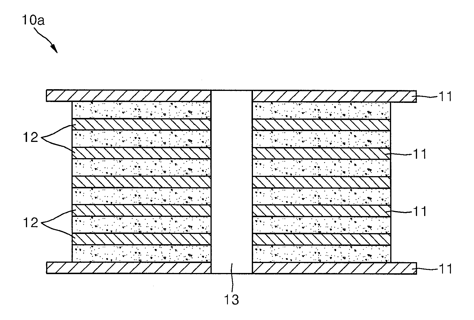
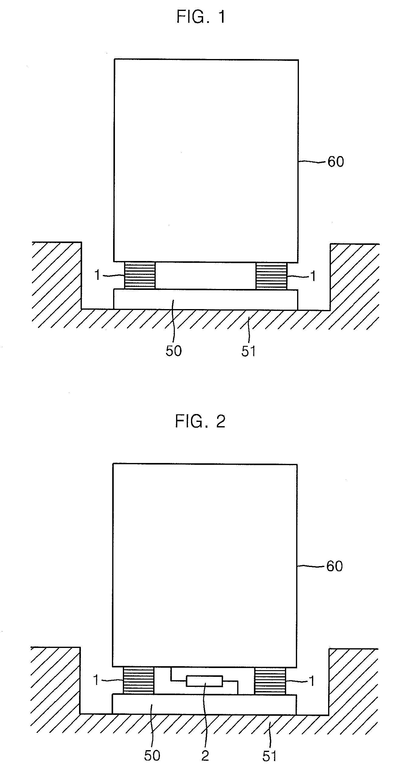
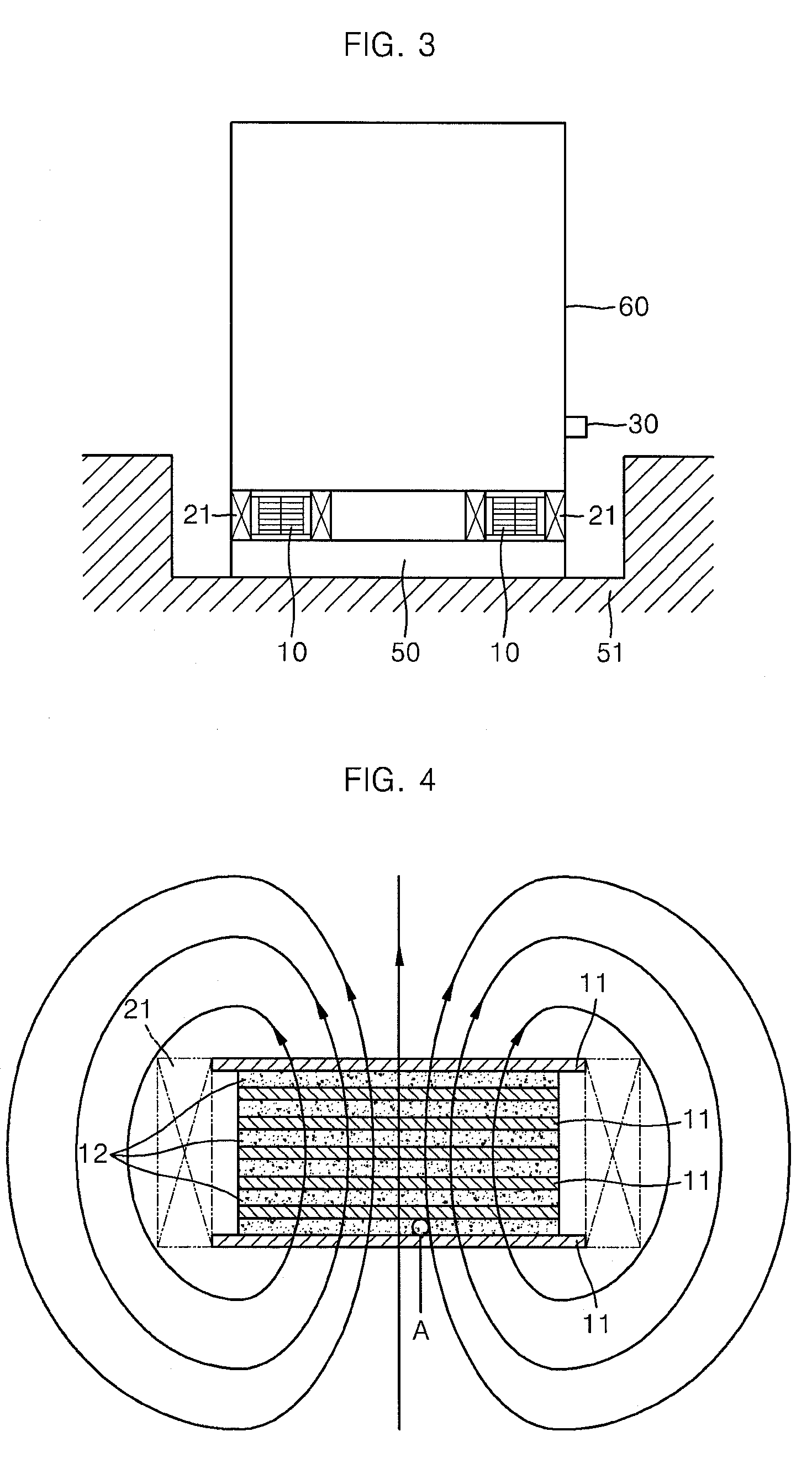
[0032]FIG. 3 is a schematic cross-sectional view of a seismic control bearing device installed in a structure in accordance with an exemplary embodiment of the present invention, FIG. 4 is a schematic cross-sectional view of a magnetic field formed in the seismic control bearing device shown in FIG. 3, FIG. 5 is an enlarged view of portion “A” of FIG. 4, and FIG. 6 is a schematic block diagram of a seismic control system including the seismic control bearing device in accordance with an exemplary embodiment of the present invention.

[0033]Referring to FIGS. 3 to 6, a seismic control system 100 in accordance with an exemplary embodiment of the present invention includes a pair of seismic control bearing devices 10, a magnetic field forming unit 20, a sensing unit 30, and a control unit 40.

[0034]As shown in FIG. ...


PUM


Abstract

Provided are a seismic control bearing device capable of absorbing and/or blocking vibration energy transmitted to structures due to earthquakes, and so on, as well as actively controlling various dynamic behaviors generated from the structures with low power and without additional equipment, and a seismic control system including the same. The seismic control bearing device is installed between a ground base and a structure constructed on the ground base to reduce vibration energy applied to the structure, and includes a plurality of deposition members spaced apart from each other; and a plurality of magneto-sensitive members disposed between the deposition members and formed of a magneto-sensitive material. The properties including a stiffness coefficient and an damping coefficient of the magneto-sensitive material are varied depending on a variation of a magnetic field formed around the magneto-sensitive member.

Description

CROSS-REFERENCE TO RELATED APPLICATION[0001]This application claims the benefit of Korean Patent Application No. 10-2006-0052880, filed on Jun. 13, 2006, the disclosure of which is hereby incorporated herein by reference in its entirety.BACKGROUND OF THE INVENTION[0002]1. Field of the Invention[0003]The present invention relates to a seismic control bearing device and a seismic control system including the same, and more particularly, to a seismic control bearing device installed in structures such as buildings, bridges, and so on, and capable of reducing vibration energy transmitted to the structures by seismic load, and a seismic control system including the same.[0004]2. Description of the Related Art[0005]In recent times, research on seismic isolation devices has been widely attempted to protect structures such as buildings, bridges, and so on, by absorbing and / or blocking vibration energy applied to the structures using additional equipment. A base isolation device such as an e...

Claims


Application Information

Patent Timeline
Patent Type & Authority Applications(United States)
IPC IPC(8): E04H9/02
CPCE04H9/022E01D19/04E04B1/36E04B1/98F16F15/04
Inventor LEE, JONG-SEHHWANG, IN-HOLIM, JONG-HYUK
Owner IUCF HYU (IND UNIV COOP FOUND HANYANG UNIV)
Why Eureka
Try Eureka