Vibration energy transmission-based vibration reduction design method for hub motor driven vehicle

A technology of vibration energy and hub motors, which is applied in mechanical equipment, combustion engines, internal combustion piston engines, etc., can solve the problems that have not been involved, and the research work of hub motor-driven vehicles is limited, so as to reduce vibration energy and improve ride comfort. Riding comfort and the effect of improving the overall performance level

Active Publication Date: 2017-11-28
SHANDONG UNIV OF TECH
View PDF7 Cites 7 Cited by
  • Summary
  • Abstract
  • Description
  • Claims
  • Application Information

AI Technical Summary

Problems solved by technology

[0003] At present, research on in-wheel motor-driven vehicles is still in its infancy, and the research work on the vibration reduction of in-wheel motor-driven vehicles is still very limited. According to the limited information retrieved so far: patent WO02 / 083446_A1 discloses an in-wheel motor and in-wheel The fixing method of the driving system, the patent CN201410520267.3 (application number), discloses a built-in suspension integrated wheel hub motor to drive the electric wheel, and the patent CN201410524767.4 (application number) discloses a hub with an electromagnetic damping device The motor drives the electric wheel. The above-mentioned patents take into account the vibration reduction problem of the hub motor driven vehicle, but the focus is on the integrated integration of the hub motor driven vehicle structure, and the vibration reduction design of the hub motor driven vehicle based on vibration energy transfer method not yet covered

Method used


Image

  • Vibration energy transmission-based vibration reduction design method for hub motor driven vehicle

Examples


Embodiment Construction

[0010] The present invention will be described in further detail below in conjunction with the accompanying drawings and implementation examples, but the embodiments of the present invention are not limited thereto.

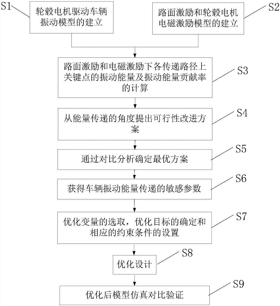
[0011] Such as figure 1 As shown in the flow chart, a vibration reduction design method for an in-wheel motor-driven vehicle proposed by the present invention, the steps include: S1: establishment of a vibration model of an in-wheel motor-driven vehicle; S2: establishment of a road excitation and in-wheel motor excitation model; S3: calculation Analyze the vibration energy and vibration energy contribution rate of each key point of the vehicle vibration model under road excitation and electromagnetic excitation; S4: Propose a feasible improvement plan from the perspective of vibration energy transfer; S5: Determine the optimal plan through comparative analysis; S6: Obtain Sensitive parameters of vehicle vibration energy transfer; S7: selection of optimization var...


PUM


Abstract

The invention discloses a vibration reduction design method for a hub motor driven vehicle. According to the technical scheme, the method comprises the steps of building physical and mathematic models of vibration of the vehicle according to the existing hub motor driven vehicle; building road surface and hub motor electromagnetic force models; through simulative analysis, performing calculation to obtain vibration energy and contribution rate of each key point under road surface and motor excitation; according to an analysis result, proposing a feasible improvement scheme, and through comparative analysis, determining an optimal scheme; obtaining sensitive parameters of vibration energy transmission of the optimal scheme; by taking minimum vibration energy transmitted to a vehicle body as an optimization goal, performing optimization design on the sensitive parameters by adopting a proper optimization algorithm; and through comparative analysis before and after optimization, verifying an optimization result, and obtaining a final design scheme. According to the vibration reduction design method provided by the invention, the vibration transmission characteristic of the hub motor driven vehicle can be effectively improved; the smoothness and riding comfort of the vehicle are improved; and a certain theoretical basis is laid for vibration reduction control of the hub motor driven vehicle.

Description

technical field [0001] The invention relates to a vibration reduction design method for an electric vehicle, in particular to a vibration reduction design method for a hub motor driven vehicle. Background technique [0002] Compared with traditional vehicles, in-wheel motor-driven vehicles cancel components such as clutches, differentials, mechanical shifting devices, and drive shafts, and highly integrated drive motors and reduction mechanisms are arranged in the wheels. This change in chassis structure , the transmission system is simplified, the transmission efficiency is improved, the effective use of space is increased, and the passing performance of the vehicle is improved. Vehicles driven by in-wheel motors have unparalleled advantages, but they also bring various new problems. Because the motor is integrated in the wheel hub, the introduction of its new power drive system and unsprung structure changes the main vibration source and transmission path of the vehicle, ...

Claims


Application Information

Patent Timeline
Patent Type & Authority Applications(China)
IPC IPC(8): G06F17/50
CPCG06F30/15G06F30/20Y02T10/40Y02T90/00
Inventor 谭迪吴延寿宋凡
Owner SHANDONG UNIV OF TECH
Why Eureka
Try Eureka