Variable area flow rate meter using optical sensing of float position in the duct

Inactive Publication Date: 2007-12-13
SMITH DANIEL J +2
View PDF16 Cites 12 Cited by
  • Summary
  • Abstract
  • Description
  • Claims
  • Application Information

AI Technical Summary

Benefits of technology

[0012] Alternatively, an optical or other sensor may be located along the length of the sensing duct, but such a sensor must be quite large and complex. Such sensing requi

Problems solved by technology

Determining the float position in the sensing duct is sometimes difficult.
Corrosive fluids may attack such magnetic materials.
Even if the magnetic material is completely embedded in the float, users are concerned that the corrosive fluid may penetrate the float and cause contamination.
Alternatively, an optica

Method used


Image

  • Variable area flow rate meter using optical sensing of float position in the duct
  • Variable area flow rate meter using optical sensing of float position in the duct
  • Variable area flow rate meter using optical sensing of float position in the duct

Examples


Embodiment Construction

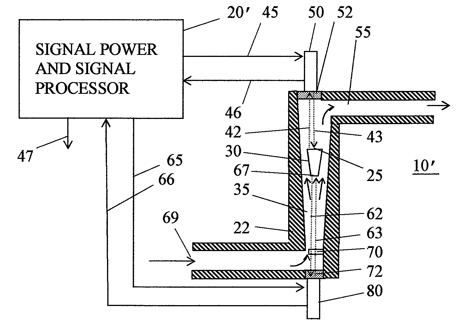
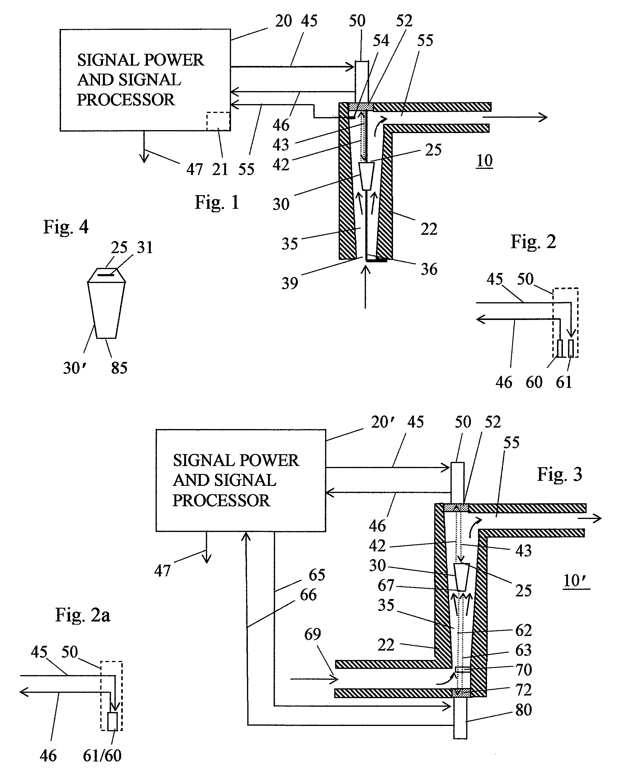
[0026]FIG. 1 shows in section a simplified variable area flowmeter 10 incorporating one version of the invention. Flowmeter 10 has a duct 35 defined by a wall 22. Duct 35 has an inlet port 39 where fluid flow enters duct 35 and an outlet port 55 where fluid exits duct 35. Duct 35 diverges upwards, so that the cross section area of duct adjacent to outlet port 55 is substantially larger than the cross section area adjacent to inlet port 39. Duct 35 has a longitudinal axis extending along the duct in the direction of fluid flow.

[0027] A float 30 is present within duct 35. The term “float” in this context is a bit misleading, since float 30 will normally, for reasons already explained, have a specific gravity substantially greater than the fluid flowing in duct 35, and thus does not float at the top of duct 35. The frustro-conical shape shown for float 30 in FIG. 1 is suitable for a variety of flowmeter designs.

[0028] The dimensions of float 30 should be sufficiently large relative t...


PUM


Abstract

A flowmeter has a variable area, vertically-oriented duct through which flows fluid whose flow rate is to be determined. A float in the duct assumes a position in the duct that depends on the flow rate of fluid in the duct. A window is located at an end of the duct in alignment with a longitudinal axis of the duct. A transducer unit projects a signal beam comprising either light in the ultraviolet, visible, or infrared spectrum, or ultrasound energy. The signal beam propagates in a beam through the window and along the axis toward the float. The transducer includes a sensor that detects the signal energy returned by the float by reflection or some other mechanism to the transducer unit. The intensity or delay time in the returned signal energy indicates the position of the float in the duct, from which the fluid flow rate may be determined.

Description

CROSS-REFERENCE TO RELATED APPLICATIONS [0001] This is a continuation in part application filed under 35 U.S.C. § 111(a) claiming priority, under 35 U.S.C. § 119, of application Ser. No. 11 / 125,500, previously filed May 10, 2005 under 35 U.S.C. § 111(b).BACKGROUND [0002] A variable area volumetric flow rate meter, hereafter simply VA flowmeter, uses a vertical sensing duct through which flows a fluid whose volumetric flow rate is to be measured. The sensing duct has a cross section area that smoothly increases along the length of the sensing bore, typically increasing upwards but that may also increase downwards. Typically, the fluid flows into an end of the duct having the smaller cross section area, and out of the duct at the larger cross section area although variations on this design are possible. [0003] In any duct of changing cross section area, velocity at each point along the duct, of a fluid flowing in the duct varies inversely to the area at that point. While the situation...

Claims


Application Information

Patent Timeline
IPC IPC(8): G01F1/66
CPCG01F1/22G01P5/02G01F15/024G01F1/24
Inventor SMITH, DANIEL J.SMISEK, QUENTINLAKHAN, HARESH
Owner SMITH DANIEL J
Why Eureka
Try Eureka