Organic Electroluminescent Element

a technology of electroluminescent elements and organic materials, applied in the direction of discharge tube/lamp details, discharge tube luminescent screens, discharge tubes/lamp details, etc., can solve the problems of low luminous efficiency, low luminous efficiency, and low reliability of bcp hole-blocking materials, so as to reduce luminous efficiency and luminous efficiency

Inactive Publication Date: 2007-12-13
NIPPON STEEL CHEMICAL CO LTD +1
View PDF5 Cites 1 Cited by
  • Summary
  • Abstract
  • Description
  • Claims
  • Application Information

AI Technical Summary

Benefits of technology

[0020] In applying organic EL elements to display devices such as flat panel displays, it is necessary to improve the luminous efficiency and at the same time to secure the driving stability. In view of the aforementioned present conditions, an object of this invention is to provide a practically useful organic EL element which performs at high efficiency, shows long lifetime, and has a simple structure. Means to Solve the Problems
[0032] The host material to be used in the light-emitting layer according to this invention allows electrons and holes to flow roughly evenly so that emission of light occurs in the center of the light-emitting layer. In the case of TAZ, emission of light occurs on the side of the hole-transporting layer thereby causing transition of energy to occur to the hole-transporting layer and lowering the luminous efficiency. On the other hand, in the case of CBP, emission of light occurs on the side of the electron-transporting layer thereby causing transition of energy to occur to the electron-transporting layer and lowering the luminous efficiency. This is not the case with the host material to be used in this invention and highly reliable materials can be used together, for example, α-NPD in the hole-transporting layer and Alq3 in the electron-transporting layer.
[0033] In particular, in the case where red light is emitted using CBP as a host material and bis(2-(2′-benzo[4,5-α]thienyl)pyridinato-N,C3′)iridium(acetylacetonate) complex [hereinafter referred to as btp2Ir(acac)] as a guest material, a technique of providing a hole-blocking layer composed of BCP or the like is known to make up for the CBP's shortcoming of facilitating the flow of holes. However, the use of a combination of materials specified by this invention can give a comparable performance in the absence of a hole-transporting layer.

Problems solved by technology

Later, europium complexes were used in an attempt to utilize the triplet state, but failed to give high luminous efficiency.
However, BCP lacks reliability as a hole-blocking material because of its tendency to crystallize even at room temperature and an element containing BCP is extremely short in lifetime.
On the other hand, BAlq is reported to provide an element with a relatively long lifetime, but it lacks a sufficient hole-blocking ability and lowers the efficiency of light emission from Ir(ppy)3.
In addition, deposition of one more layer makes the structure of an element more complex and raises the manufacturing cost.
For example, 4,4′-bis[N-(1-naphthyl)-N-phenylamino]biphenyl (hereinafter referred to as α-NPD) is used most frequently as a hole-transporting layer because of its excellent performance, high reliability, and long lifetime; however, it shows poor affinity with Ir(ppy)3 and transition of energy occurs from TAZ to α-NPD thereby lowering the efficiency of transition of energy to Ir(ppy)3 and dropping the luminous efficiency.
However, HMTPD tends to crystallize easily as its glass transition temperature (hereinafter referred to as Tg) is approximately 50° C. and lacks reliability as an electroluminescent material.
In consequence, there are also other problems such as extremely short lifetime of element, difficulty of commercial application, and high driving voltage.
However, this does not teach phosphorescent luminescence.

Method used


Image

  • Organic Electroluminescent Element
  • Organic Electroluminescent Element
  • Organic Electroluminescent Element

Examples


example 1

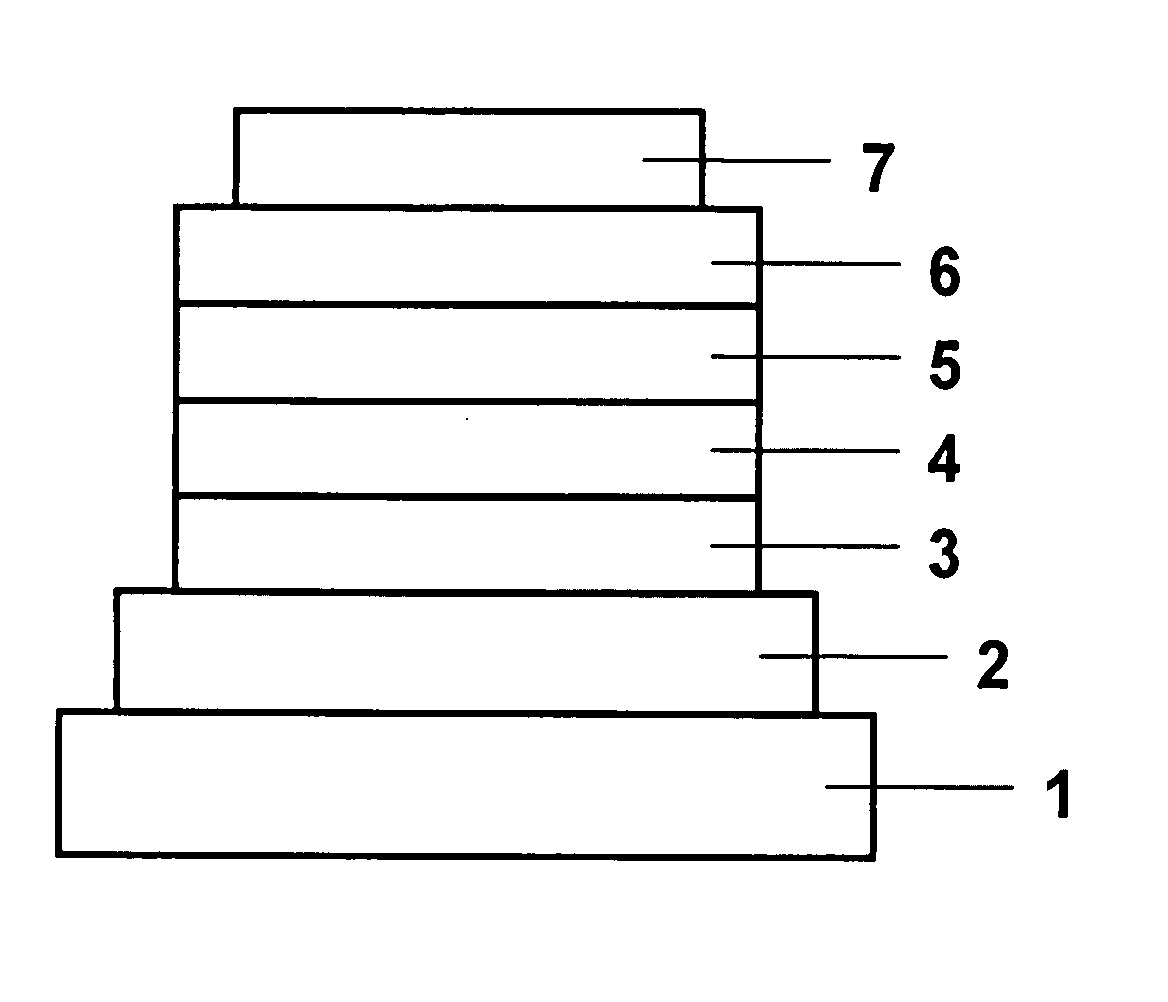
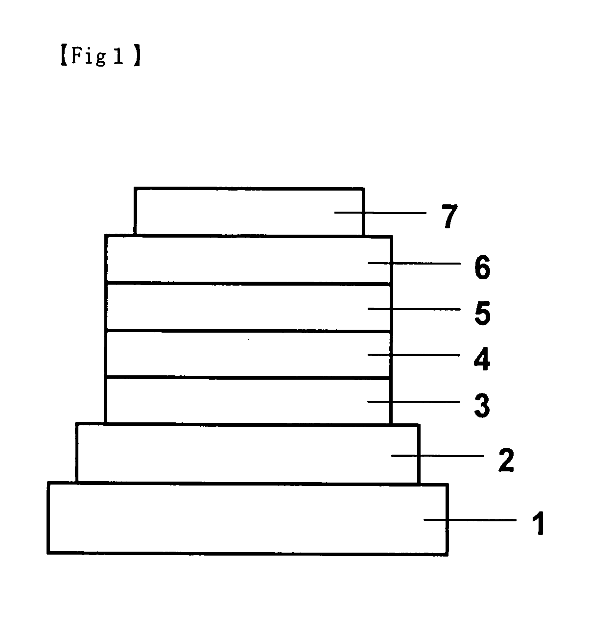
[0059] Copper phthalocyanine (CuPC), α-NPD, and Alq3 were used respectively for forming a hole-injecting layer, a hole-transporting layer, and an electron-transporting layer by vacuum-depositing one compound upon another in thin film at a degree of vacuum of 5.0×10⁻⁴ Pa on a glass substrate on which a 110 nm-thick ITO anode had been formed. First, CuPC was deposited on the ITO anode at a rate of 3.0 Å / s to a film thickness of 25 nm to form a hole-injecting layer. On this hole-injecting layer was deposited α-NPD at a rate of 3.0 Å / s to a film thickness of 55 nm to form a hole-transporting layer. Å

[0060] Following this, a light-emitting layer was formed by co-vacuum-depositing Compound 1 and btp2Ir(acac) on the hole-transporting layer from different evaporation sources to a thickness of 47.5 nm. The concentration of btp2Ir(acac) at this point was 7.0%. Then, Alq3 was deposited at a rate of 3.0 Å / s to a thickness of 30 nm to form an electron-transporting layer.

[0061] Further, an elect...


PUM


Abstract

This invention relates to an organic electroluminescent element (organic EL element) utilizing phosphorescence which shows improved luminous efficiency and driving stability and has a simple structure. The organic EL element comprises an anode, organic layers containing a hole-transporting layer, a light-emitting layer, and an electron-transporting layer, and a cathode piled one upon another on a substrate with the hole-transporting layer disposed between the light-emitting layer and the anode and the electron-transporting layer disposed between the light-emitting layer and the cathode. The light-emitting layer contains a compound represented by the following general formula (I) as a guest material and an organic metal complex containing at least one metal selected from ruthenium, rhodium, palladium, silver, rhenium, osmium, iridium, platinum, and gold as a guest material; in general formula (I), R1-R6 are independently hydrogen atoms, alkyl groups, aralkyl groups, alkenyl groups, cyano groups, alkoxy groups, aromatic hydrocarbon groups, or aromatic heterocyclic groups.

Description

FIELD OF TECHNOLOGY [0001] This invention relates to an organic electroluminescent element (hereinafter referred to as an organic EL element) and, more particularly, to a thin-film device which emits light when an electrical field is applied to its organic light-emitting layer. BACKGROUND TECHNOLOGY [0002] In the development of electroluminescent elements utilizing organic materials, the kind of electrodes was optimized for the purpose of improving the electron-injecting efficiency from the electrode and an element in which a hole-transporting layer composed of an aromatic diamine and a light-emitting layer composed of 8-hydroxyquinoline aluminum complex (hereinafter referred to as Alq3) are disposed as thin films between the electrodes was developed to bring about a noticeable improvement in luminous efficiency over the conventional elements utilizing single crystals of anthracene and the like. Following this, the developmental works of organic EL elements have been focused on thei...

Claims


Application Information

Patent Timeline
Patent Type & Authority Applications(United States)
IPC IPC(8): H01J1/63
CPCC09K11/06C09K2211/1007C09K2211/1029C09K2211/1037C09K2211/1092H05B33/14C09K2211/186H01L51/0081H01L51/0085H01L51/0087H01L51/5016C09K2211/185H10K85/324H10K85/346H10K85/342H10K50/11H10K2101/10
Inventor MATSUO, SHINJIMIYAZAKI, HIROSHITSUJI, TAISHI
Owner NIPPON STEEL CHEMICAL CO LTD
Why Eureka
Try Eureka