Airborne Look-Down Doppler Radar Tracking of Hovering Helicopters using Rotor Features

Active Publication Date: 2007-12-13
RAYTHEON CO
View PDF9 Cites 15 Cited by
  • Summary
  • Abstract
  • Description
  • Claims
  • Application Information

AI Technical Summary

Benefits of technology

[0013]This is accomplished by a missile radar which receives radar returns, processes the returns to create a 1-D Doppler profile or 2-D Range-Doppler Map (“Doppler Map”), and distinguishes a helicopter's extended rotor return from both clutter and body returns. The Doppler map contains both amplitude and Doppler shift information. If the missile detects a potential target in the Doppler map, it will typically try to classify the potential target using conventional body Doppler techniques. If the body Doppler fails to classify the target or is inconclusive, “rotor samples” are identified from the samples within the extended rotor return. To facilitate identification, search window(s) arc suitably modified to exclude clutter and body return and capture the maximum Doppler shift of the rotor assembly.
[0014]The extended rotor return is not merged with clutter because the rotor assembly rotates at a sufficiently high rate to produce a significant Doppler shift. Performance may be improved by using a pulsed-radar with a medium pulse repetition frequency (PRF) which eliminates ground clutter in other range gates in the Range-Doppler Map from being integrated into the Doppler filters for the range gate that includes the potential target while maintaining sufficient Doppler resolution. The samples within the modified search window(s) are compared to a threshold T2 set an increment above, for example, the CFAR threshold T1 which is referenced to the noise floor of the system and a threshold T3 below the body return (if available) to identify r

Problems solved by technology

The helicopter is a particularly difficult target for air- or surface-launched missiles that use airborne look-down Doppler radars.
Speeds that range from over 200 knots to a hover, extremely low-altitude flight, an ability to terrain mask or hide using terrain features and an ability to employ a wide variety of lethal ordnance are some of a helicopter's challenging characteristics.
Ground-laun

Method used


Image

  • Airborne Look-Down Doppler Radar Tracking of Hovering Helicopters using Rotor Features
  • Airborne Look-Down Doppler Radar Tracking of Hovering Helicopters using Rotor Features
  • Airborne Look-Down Doppler Radar Tracking of Hovering Helicopters using Rotor Features

Examples


Example

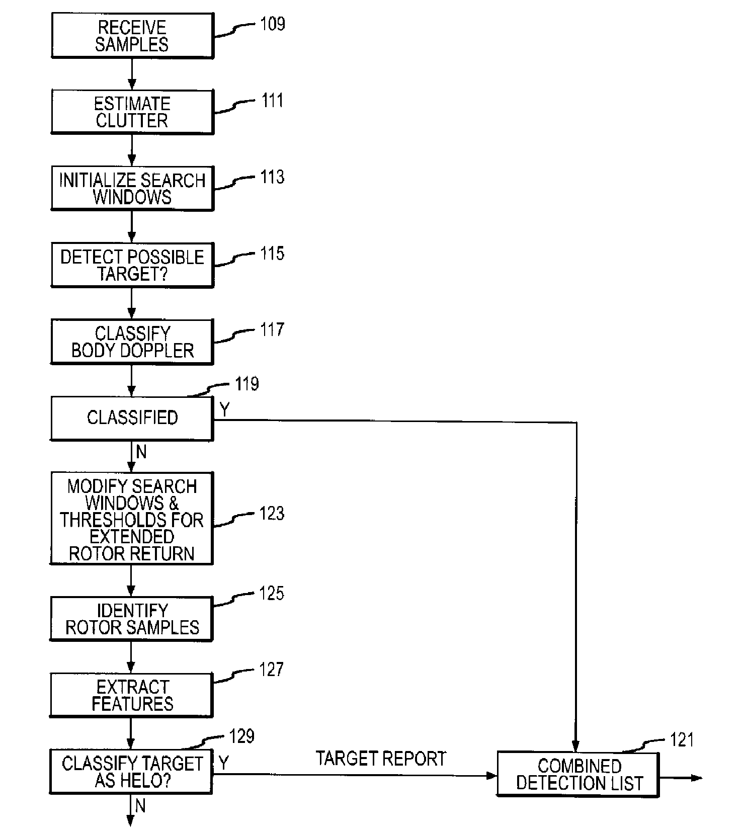
[0024]The present invention describes a system and method for detecting and classifying slow-moving and hovering helicopters from a missile's look-down Doppler radar that is compatible with the existing base of Doppler radars. This approach uses definable attributes of a helicopter rotor assembly and its extended Doppler rotor return to (a) differentiate “rotor samples” from other samples, (b) extract features such as bandwidth activity, angle, and shape from the rotor samples, (c) classify a potential target as a helicopter or other based on the extracted rotor features and the known attributes of the helicopter rotor assembly. Once classified, a target report including a helo classification tag, range, range-rate and angle is suitably passed to the tracking processor.

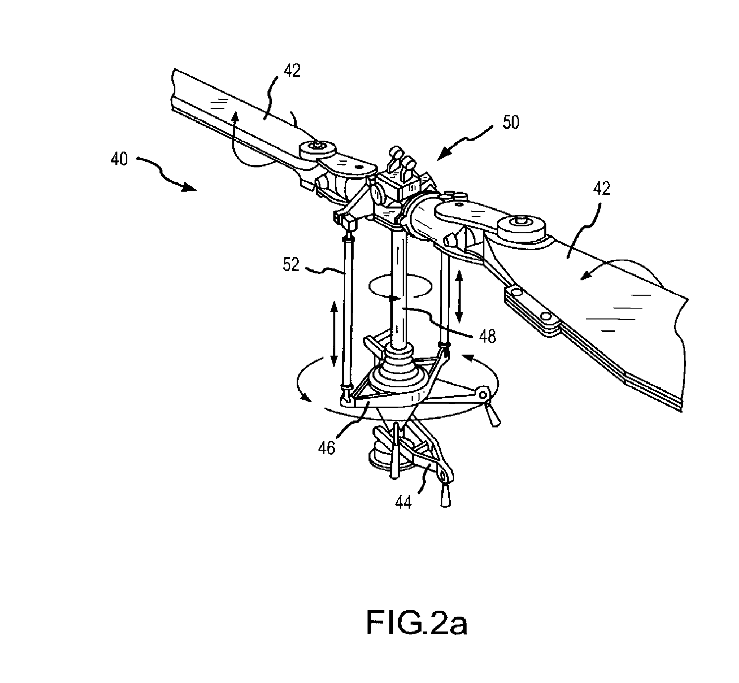
[0025]As shown in FIG. 2a, a typical two-bladed helicopter rotor assembly 40 provides a helicopter with the power necessary to rotate main rotor blades 42, generate lift and thrust, and to move laterally, turn, and ch...


PUM


Abstract

A system and method is presented for detecting and classifying slow-moving and hovering helicopters from a missile's took-down Doppler radar that is compatible with the existing base of Doppler radars. This approach uses definable attributes of a helicopter rotor assembly and its extended Doppler rotor return to differentiate “rotor samples” from other samples (steps 123, 125), extract features such as bandwidth, activity, angle, and shape from the rotor samples (step 127), and classify a potential target as a helicopter or other based on the extracted rotor features and the known attributes of the helicopter rotor assembly (step 129). A target report including a classification target, range, range-rate, and angle of the extended rotor return is suitably passed to a tracking processor (step 121).

Description

BACKGROUND OF THE INVENTION[0001]1. Field of the Invention[0002]This invention relates to airborne look-down Doppler radars and, more particularly, to a system and method for extracting rotor features from a Doppler radar to track hovering helicopters.[0003]2. Description of the Related Art[0004]The significance of the helicopter threat continues to grow as U.S. interests are challenged in austere, worldwide locations by conventional forces and terrorist organizations employing unconventional, asymmetric means of warfare. Without an ability to field a conventional air force, adversaries place greater emphasis on the wide range of missions which can be conducted by a relatively inexpensive helicopter force. The helicopter is a particularly difficult target for air- or surface-launched missiles that use airborne look-down Doppler radars. Speeds that range from over 200 knots to a hover, extremely low-altitude flight, an ability to terrain mask or hide using terrain features and an abi...

Claims


Application Information

Patent Timeline
IPC IPC(8): G01S7/34G01S7/41G01S13/66
CPCG01S7/414G01S7/415G01S13/883G01S13/72G01S13/5244
Inventor RADZA, BERNARD P.HENNING, JOSEPHALI, SUNNYMINCER, JOHNWALTERS, RANDAL
Owner RAYTHEON CO
Why Eureka
Try Eureka