Distortion Compensating Apparatus

a compensating apparatus and distortion compensation technology, applied in the direction of digital transmission, amplifier modification to reduce non-linear distortion, baseband system details, etc., can solve the problems of not describing a concrete error detecting method or adjustment method, deteriorating distortion compensation performance, etc., to prevent the deterioration of distortion compensation performance

Inactive Publication Date: 2007-12-13
MITSUBISHI ELECTRIC CORP
View PDF5 Cites 22 Cited by
  • Summary
  • Abstract
  • Description
  • Claims
  • Application Information

AI Technical Summary

Benefits of technology

[0015] The present invention can obtain the IQ imbalance compensation coefficients in real time using any given transmission signal. Consequently the present invention offers an advantage of being able to compensate

Problems solved by technology

As shown in Patent Document 1, for example, a conventional distortion compensating apparatus has a problem in that its distortion compensation performance deteriorates because of the gain error and phase shift error of the π/2 phase shifter between the in-phase (I) channel component and quadrature (Q) channel component in a quadrature modulation circuit or quadrature demodulation circuit.
However, it does not describe a concrete error detecting method or adjusting method.
However, mobile communication or broadcasting base station equipment to which the distortion compensating apparatus is applied cannot transmit the particular test signal after their operation has been sta

Method used


Image

  • Distortion Compensating Apparatus
  • Distortion Compensating Apparatus
  • Distortion Compensating Apparatus

Examples


embodiment 1

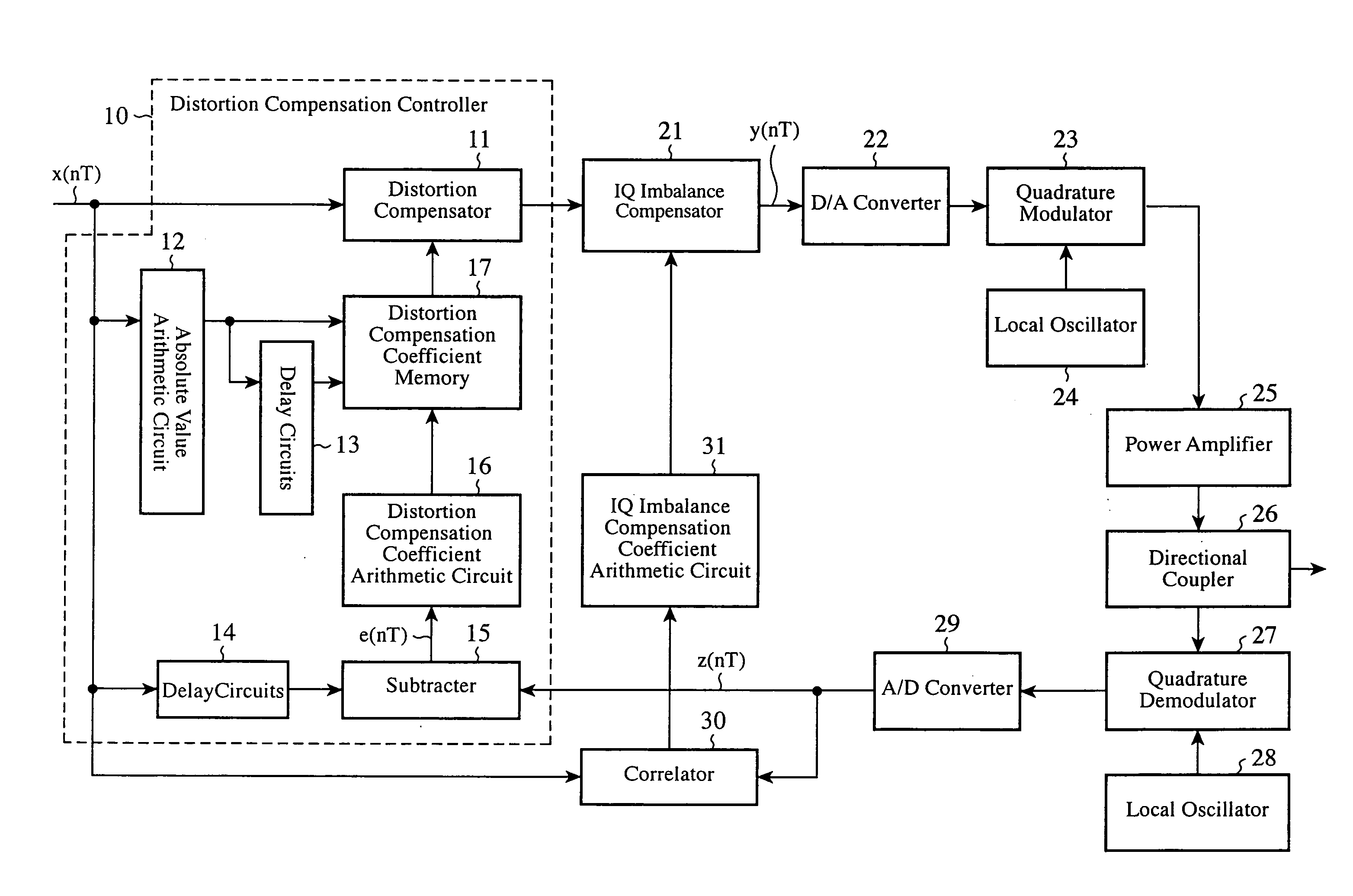
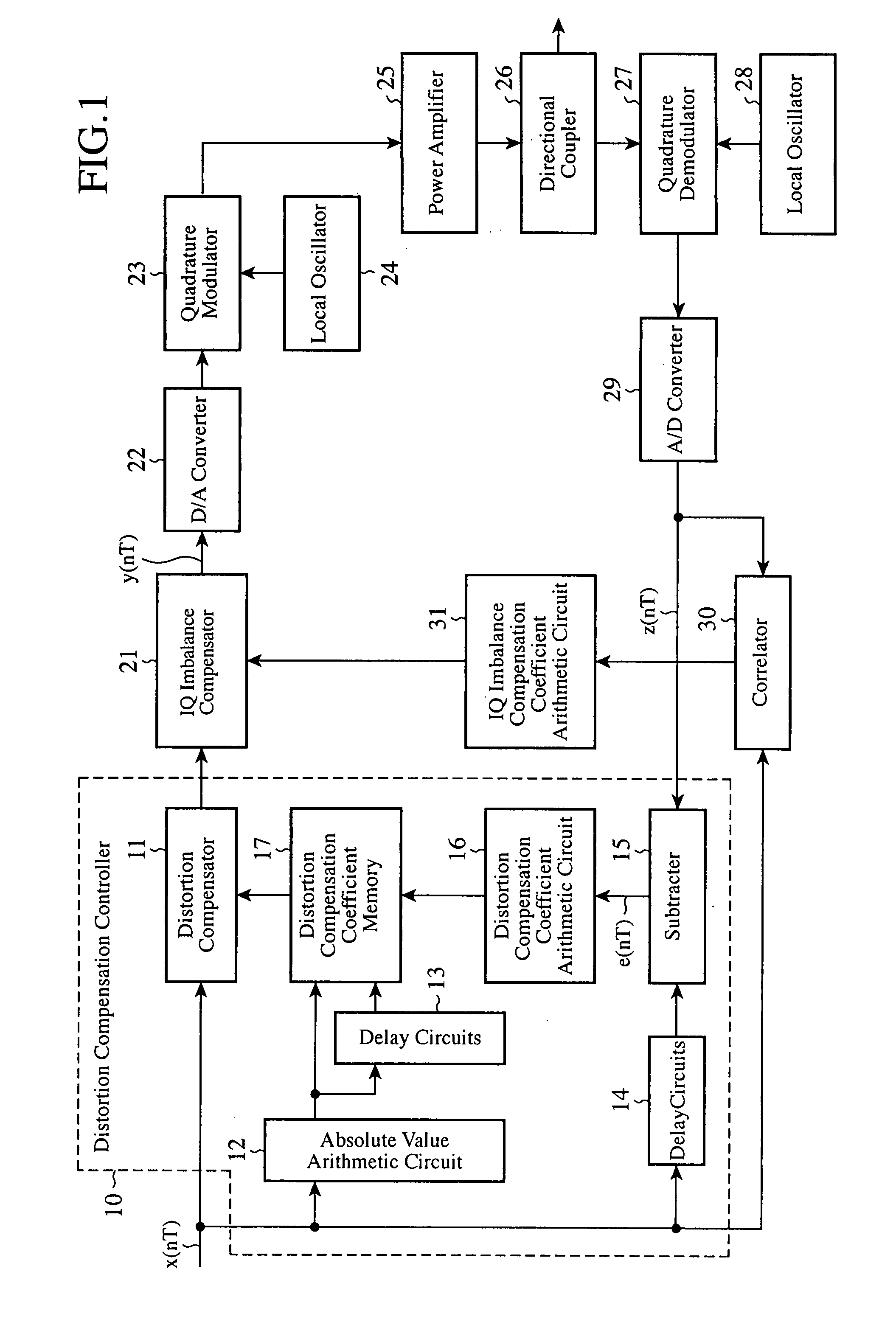
[0020]FIG. 1 is a block diagram showing a configuration of the distortion compensating apparatus of an embodiment 1 in accordance with the present invention. The distortion compensating apparatus has a distortion compensation controller 10, an IQ imbalance compensator 21, a D / A (digital / analog) converter 22, a quadrature modulator 23, a local oscillator 24, a power amplifier 25, a directional coupler 26, a quadrature demodulator 27, a local oscillator 28, an A / D (analog / digital) converter 29, a correlator 30 and an IQ imbalance compensation coefficient arithmetic circuit 31.

[0021] The distortion compensation controller 10 has a distortion compensator 11, an absolute value arithmetic circuit 12, delay circuits 13 and 14, a subtracter 15, a distortion compensation coefficient arithmetic circuit 16, and a distortion compensation coefficient memory 17.

[0022] Next, the operation will be described.

[0023] The distortion compensator 11 of the distortion compensation controller 10 compens...

embodiment 2

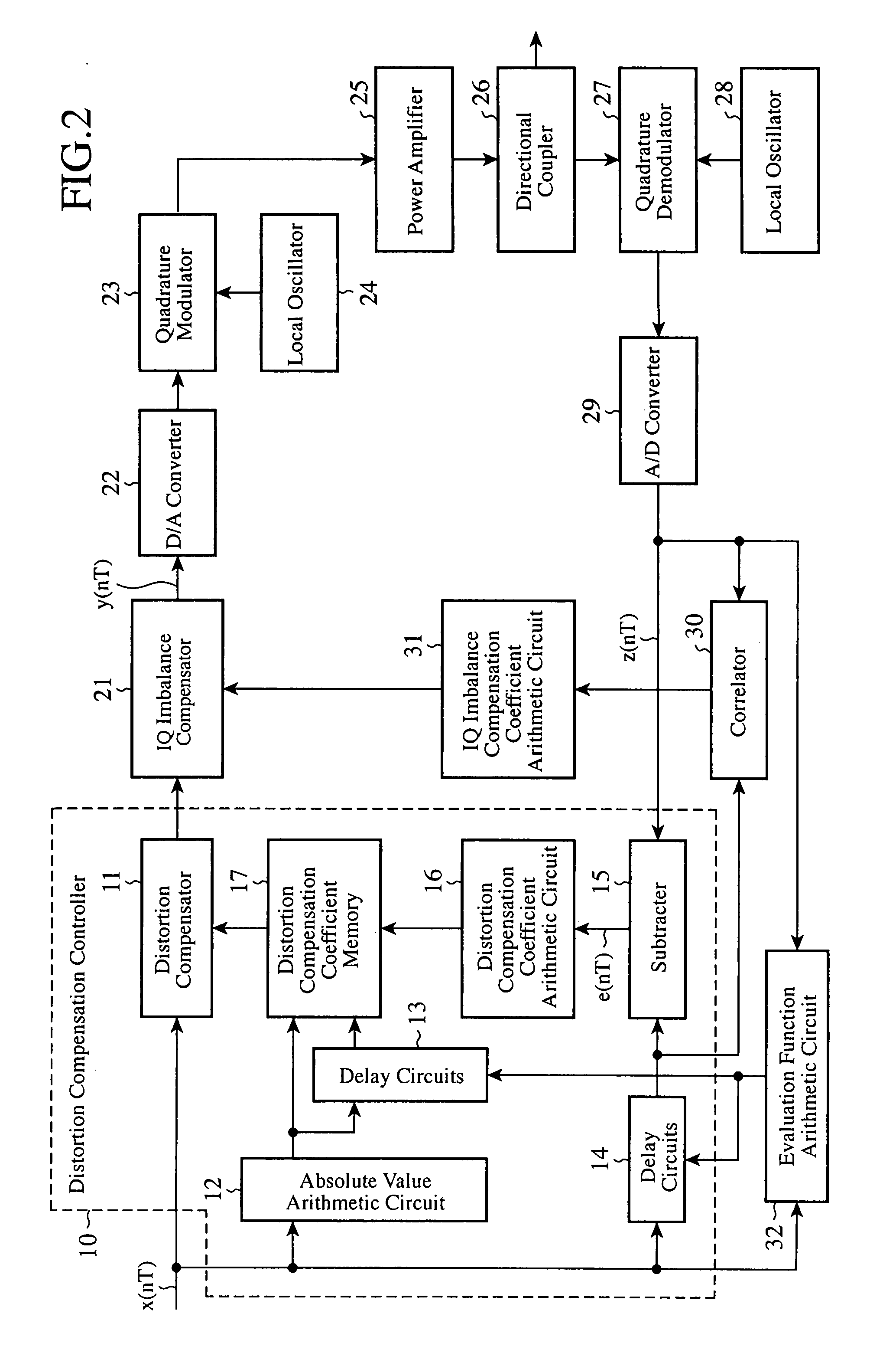
[0041] The foregoing embodiment 1 assumes that the timings between the feedback signal z(nT) and transmission signal x(nT) are adjusted by the delay circuits 13 and 14. Even in the case where the timings between the feedback signal z(nT) and transmission signal x(nT) are off, and in addition, the IQ imbalance occurs, the present embodiment 2 carries out the IQ imbalance compensation after making timing adjustment.

[0042]FIG. 2 is a block diagram showing a configuration of the distortion compensating apparatus of an embodiment 2 in accordance with the present invention, which includes an evaluation function arithmetic circuit 32 in addition to the foregoing embodiment 1 shown in FIG. 1. In FIG. 2, since the remaining components are the same as those of FIG. 1, they are designated by the same reference numerals and their description will be omitted here.

[0043] Next the operation will be described.

[0044] The evaluation function arithmetic circuit 32, varying the delay τ of the transm...


PUM


Abstract

A distortion compensating apparatus has an IQ imbalance compensation coefficient arithmetic circuit 31 for calculating, from correlation values of a transmission signal and a feedback signal, IQ imbalance compensation coefficients for compensating for IQ imbalance in a quadrature modulator 23; and an IQ imbalance compensator 21 for compensating for the IQ imbalance with respect to a distortion compensated signal output from a distortion compensator 11 according to the IQ imbalance compensation coefficients, and for outputting to the quadrature demodulator 23.

Description

TECHNICAL FIELD [0001] The present invention relates to a distortion compensating apparatus for compensating for nonlinear distortion of a power amplifier for amplifying a transmission signal. BACKGROUND ART [0002] As shown in Patent Document 1, for example, a conventional distortion compensating apparatus has a problem in that its distortion compensation performance deteriorates because of the gain error and phase shift error of the π / 2 phase shifter between the in-phase (I) channel component and quadrature (Q) channel component in a quadrature modulation circuit or quadrature demodulation circuit. Here, the gain error and the phase shift error are collectively called IQ imbalance. [0003] In contrast with this, the Patent Document 1 circuit, in addition to the conventional distortion compensation circuit, compensates for the IQ imbalance by causing a waveform generating circuit to output a predetermined baseband signal, and by installing an error measuring circuit for measuring a d...

Claims


Application Information

Patent Timeline
IPC IPC(8): H03F1/32
CPCH03F1/3247H03F1/3294H04L2027/0016H04L27/364H03F2200/336
Inventor HAYASHI, RYOJIANDO, NOBUHIKO
Owner MITSUBISHI ELECTRIC CORP
Why Eureka
Try Eureka