System and method for lumbar arthroplasty

a lumbar arthroplasty and system technology, applied in the field of system and method of lumbar arthroplasty, can solve the problems of increased pain, hypertrophy and/or fusion, and further premature degeneration of adjacent levels of the spinal segmen

Inactive Publication Date: 2007-12-13
SPINADYNE
View PDF99 Cites 58 Cited by
  • Summary
  • Abstract
  • Description
  • Claims
  • Application Information

AI Technical Summary

Benefits of technology

[0012]The present invention advantageously provides a method and system for lumbar arthroplasty including a vertebral disc prosthesis may be provided for insertion between first and second vertebral bodies to provide for the movement and articulation thereof. The vertebral disc prosthesis may include an articulating surface and/or mechanism, such as a hinge, ball-and-joint type structure, or simply a contoured surface, each of which would provide for the articulation of the first and second vertebral bodies upon implantation of the disc prosthesis therebetween. Moreover, the movement afforded to the first and second vertebral bodies due to the intervertebral disc prosthesis may define a center of rotation or movement.
[0013]The present invention may further include a stabilization element affixed to both the first and second vertebral bodies to provide added support and/or to control the range of motion of the spinal segment. The stabilization element may provide a range of motion in conjunction with the movement of the first and second vertebral bodies, wherein the range of motion of the stabilization element defines a center of rotation and/or movement. For example, the stabilization element may include a first por

Problems solved by technology

As such, additional stress could be experienced and lead to further premature degeneration of the adjacent levels of the spinal segment.
With the onset of degeneration, this center of rotation may shift in an unpredictable manner.
On the other hand, if the center of rotation of the disc prosthesis is not similar to that of a normal, healthy segment, the facet joi

Method used


Image

  • System and method for lumbar arthroplasty
  • System and method for lumbar arthroplasty
  • System and method for lumbar arthroplasty

Examples


Embodiment Construction

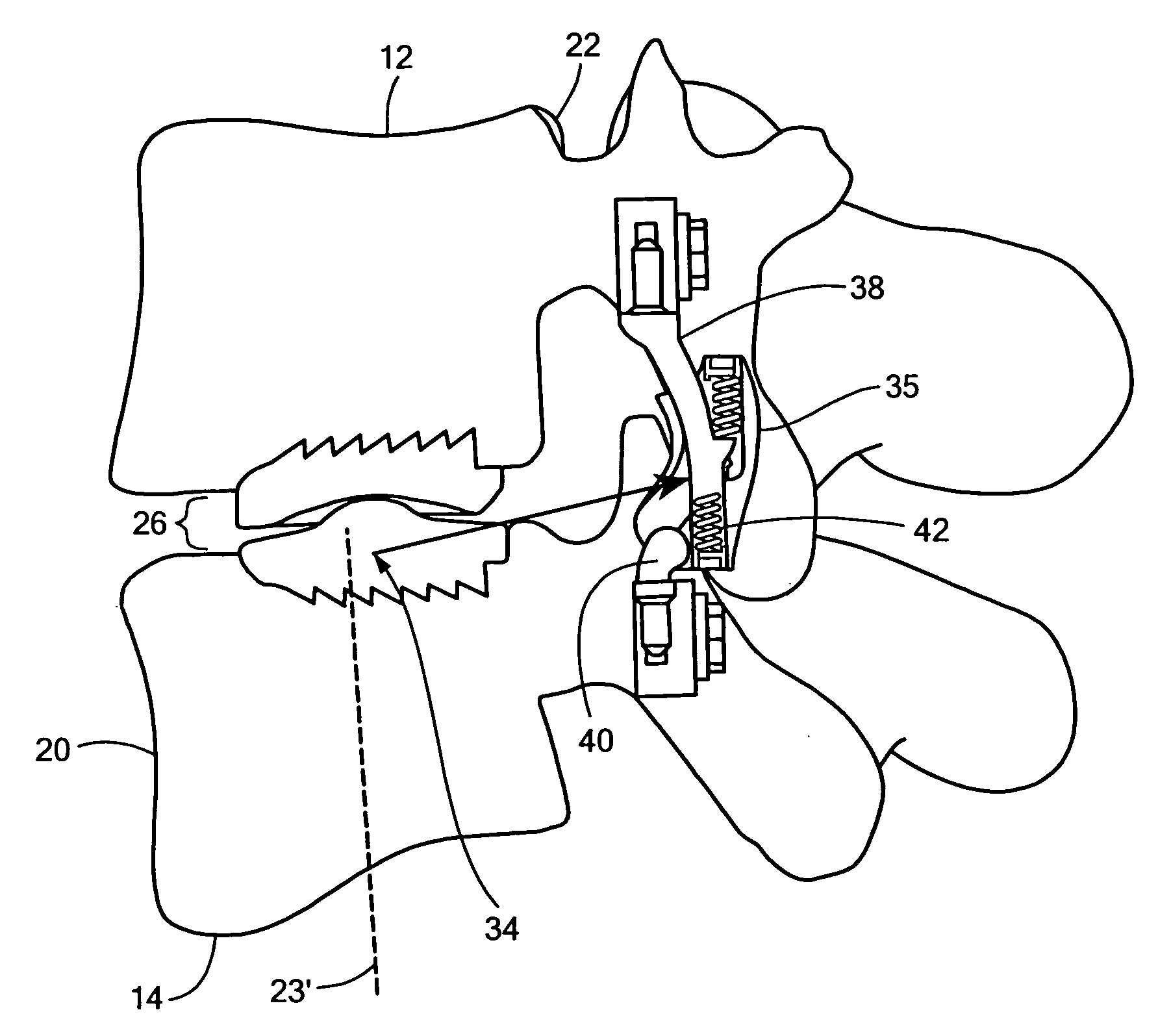
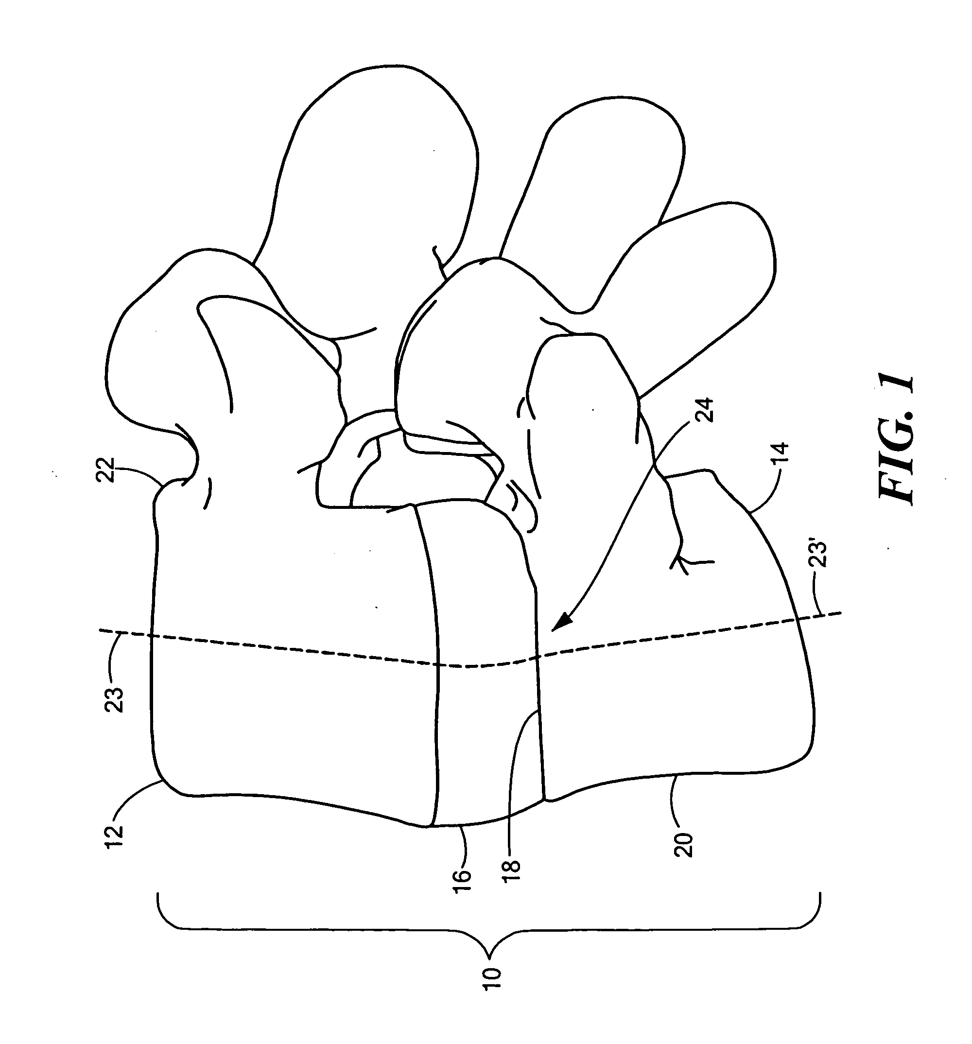
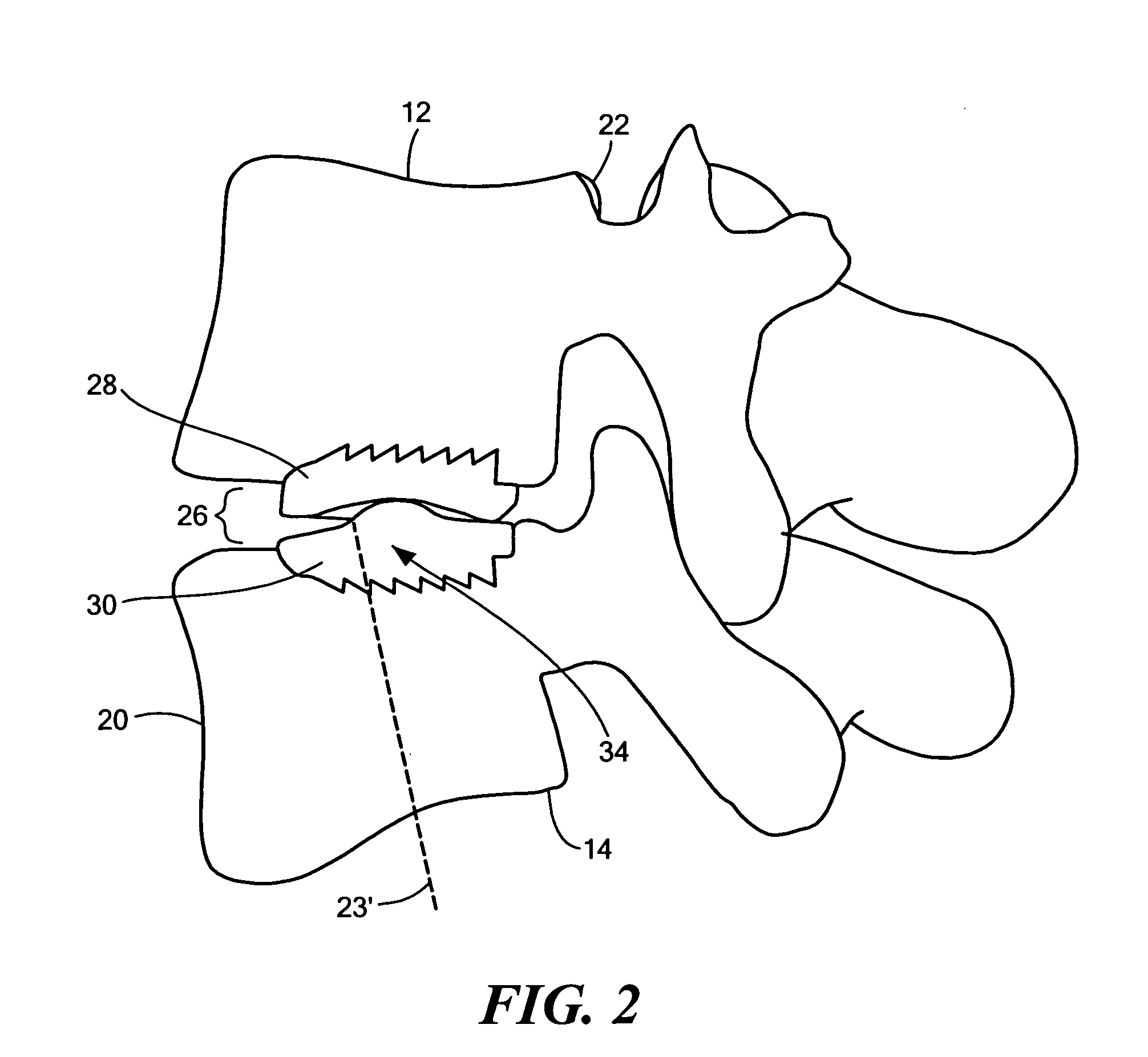
[0023]The present invention provides a system and method for spinal arthroplasty in a spinal segment. Primarily, the human spine consists of multiple spinal segments, with a spinal segment 10 having first and second vertebral bodies 12, 14 with an intervertebral disc 16 located therebetween, as shown in FIG. 1. Moreover, the spinal segment 10 typically includes a vertebral endplate 18, which is a thin layer of cartilage located between the vertebral body and the intervertebral disc 16. The vertebral bodies include both an anterior portion 20 and a posterior portion 22 corresponding to the “front” end and “back” end, respectively, of the spinal column as is known in the art. Each of the first and second vertebral bodies further define a midline 23, 23′ equidistant from their respective anterior and posterior faces. As discussed above, each segment of the spine moves around an instantaneous point of rotation, where the point of rotation 24 is typically located next to the upper endpla...


PUM


Abstract

The present invention provides a system and method for lumbar arthroplasty in a spinal segment having first and second vertebral bodies, where a intervertebral disc prosthesis may be provided and positioned between the first and second vertebral bodies such that a center of rotation of movement of the vertebral bodies about the prosthesis is located substantially proximate to the upper endplate of the second vertebral body and substantially proximate to the posterior one-third portion of the second vertebral body. In addition, a stabilization element may be affixed to the first and second vertebral bodies such that a range of motion of the stabilization device defines a center of rotation substantially proximate to that of the intervertebral disc prosthesis.

Description

CROSS-REFERENCE TO RELATED APPLICATION[0001]This application is related to and claims priority to U.S. Provisional Patent Application Ser. No. 60 / 812,032 filed Jun. 08, 2006, entitled SYSTEM AND METHOD FOR LUMBAR ARTHROPLASTY, the entirety of which is incorporated herein by reference.STATEMENT REGARDING FEDERALLY SPONSORED RESEARCH OR DEVELOPMENT[0002]n / aFIELD OF THE INVENTION[0003]The present invention relates to a system and method for lumbar arthroplasty, and more particularly, to a system having a posterior lumbar disc replacement and a posterior dynamic stabilization device having matched centers of rotation.BACKGROUND OF THE INVENTION[0004]Prior to the availability of lumbar arthroplasty, interbody fusion was the primary treatment modality for symptomatic lumbar disc disease. This procedure could typically remove the pain generator from the disc, but results could also include at least some loss in the ability to absorb shock, as well as a reduction in the range of motion of t...

Claims


Application Information

Patent Timeline
IPC IPC(8): A61F2/44A61B17/70
CPCA61F2/08A61F2/4405A61F2/4425A61F2002/30563A61F2002/30904A61F2002/30601A61F2002/30624A61F2002/30649A61F2002/30566
Inventor KRISHNA, MANOJFRIESEM, TAI
Owner SPINADYNE
Why Eureka
Try Eureka