Apparatus and Method for Managing Supply of Additive at Wellsites

Inactive Publication Date: 2007-12-20
BAKER HUGHES INC
View PDF58 Cites 99 Cited by
  • Summary
  • Abstract
  • Description
  • Claims
  • Application Information

AI Technical Summary

Benefits of technology

[0012] A system and method for managing the supply of an additive at a well site is disclosed that include supplying the additive into a well from a source thereof at a first injection rate into one or more production zones of well; determining a formation fluid flow rate for the fluid produced by the wellbore; determining a second injection rate corresponding to the determined fluid flow rate; and adjusting the additive injection rate to the second injection rate. The method and system utilize a computer model that utilizes a plurality of inputs stored in a database and measurements made during the production of the fluids from the well. The computer model and other computer

Problems solved by technology

A substantial number of wells are unmanned.
Additive injection systems used at such wells are often not serviced routinely, which can result in the malfunction of such a system, thereby either injecting incorrect amounts of additives or in some cases becoming totally inoperative.
Injecting excessive amounts of additives can increase the operating cost of the well, while inadequate amounts of the additives can cause the formation of scale, corrosion, hydrate, emulsion, asphaltene.
Inadequate or incorrect supply of additives can cause the build-up of chemicals such as cale, hydrate, paraffin, emulsion, corrosion, asphaltene, etc., which can: clog and corrode downhole equipment; reduce hydrocarbon production from the well; reduce the operating life of the well equipment; reduce the operating life of the well itself; require expensive rework operations; or cause the abandonment of the well.
Excessive corrosion in a pipeline, especially in a subsea pipeline, can reduce the flow through the pipeline or rupture the pipeline and contaminate the surrounding environment.
Repairing subsea pipelines can be cost-prohibitive.
Such systems typ

Method used


Image

  • Apparatus and Method for Managing Supply of Additive at Wellsites
  • Apparatus and Method for Managing Supply of Additive at Wellsites
  • Apparatus and Method for Managing Supply of Additive at Wellsites

Examples


Embodiment Construction

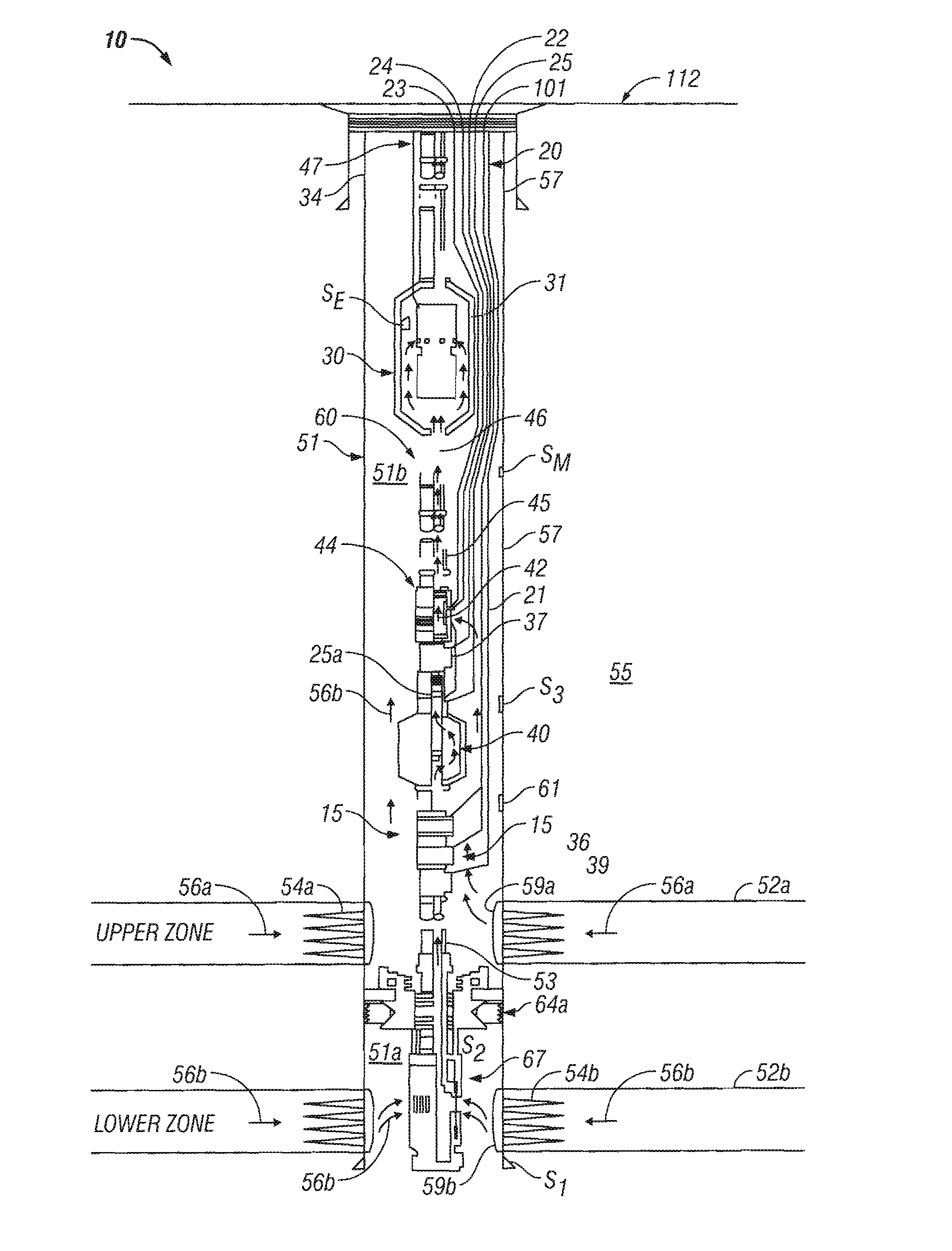
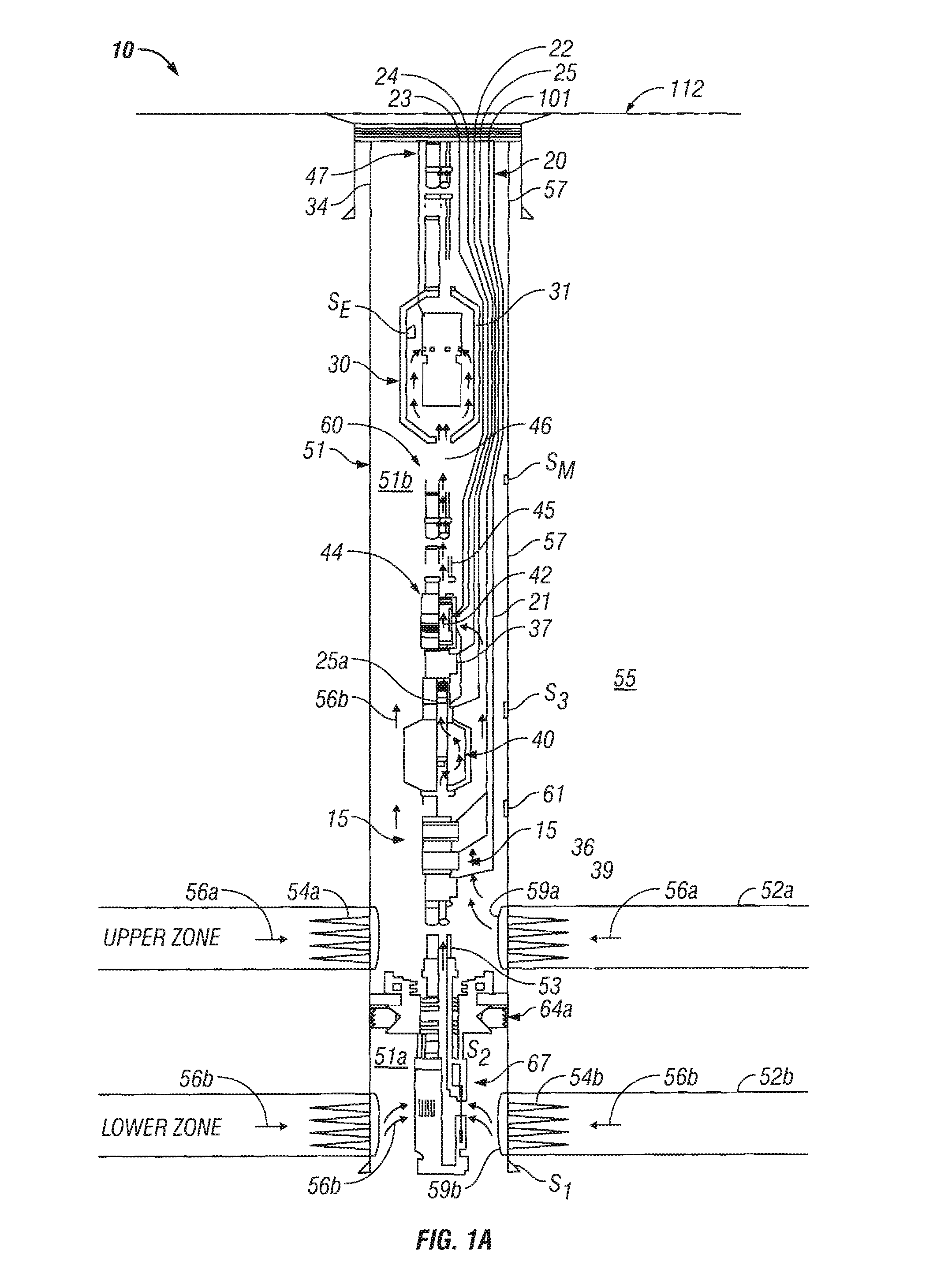
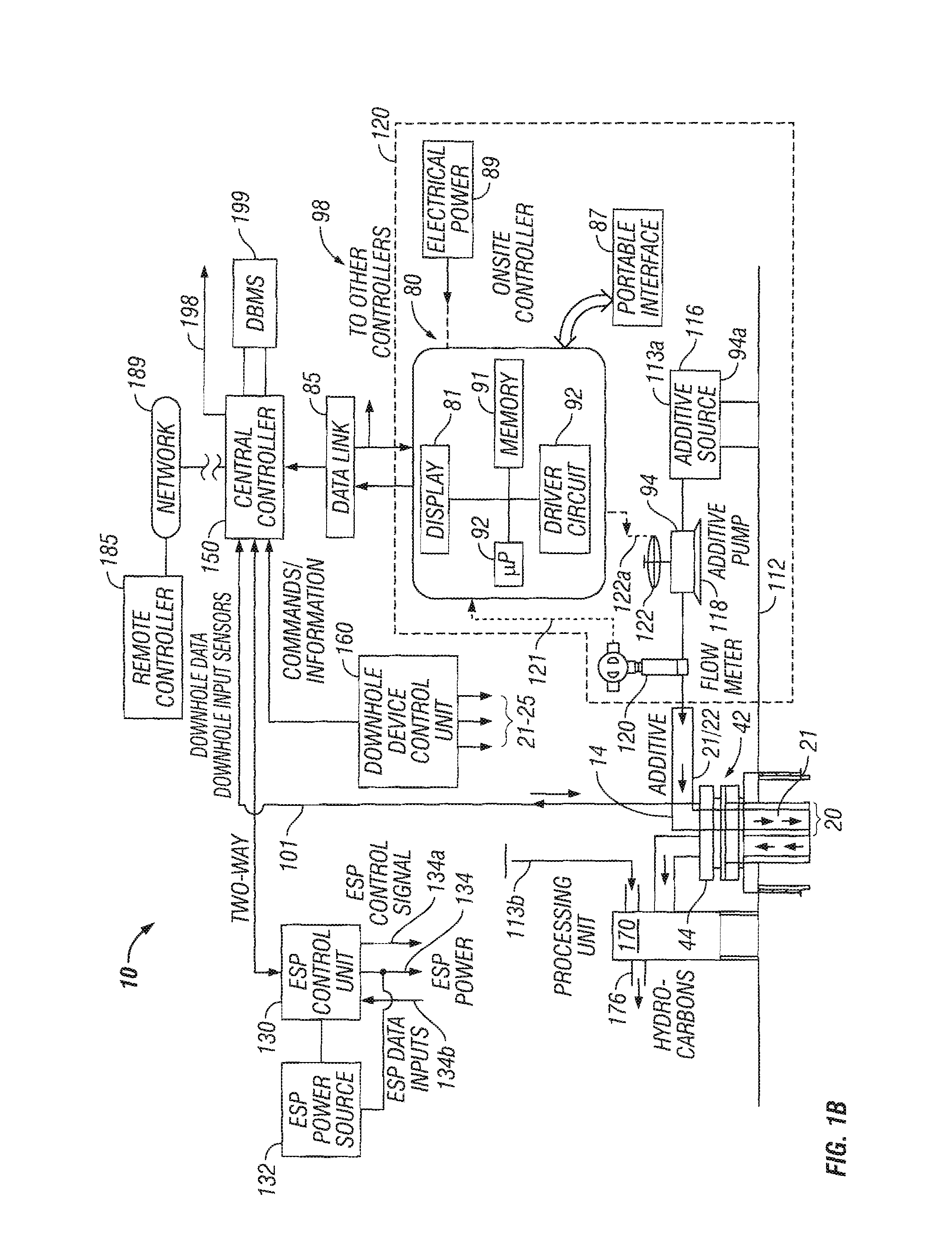
[0017]FIGS. 1A and 1B collectively show a schematic diagram of a wellsite additive management system 10, according to one embodiment of the disclosure. FIG. 1A shows a production wellbore 50 that has been configured using exemplary equipment, devices and sensors that may be utilized to implement the concepts and methods described herein. FIG. 1B shows exemplary surface equipment, devices, controllers and sensors that may be utilized to manage the operation of various devices in the system 10, including the supply of the additives into the well and the surface equipment in response to the downhole conditions, surface conditions and according to programmed instruction, and / or a nodal analysis, use of a neural network or other algorithms. In one aspect, the system 10 manages the supply of the additives to one or more locations in the wellbore and in another aspect manages the supply of additives to the surface fluid treatment and processing units and the pipelines at the well site that...


PUM


Abstract

A system and method for supplying an additive into a well is disclosed that includes estimating injection rates for the additives and setting of one or more fluid flow control devices in the well based on a computer model. It is emphasized that this abstract is provided to comply with the rules requiring an abstract which will allow a searcher or other reader to quickly ascertain the subject matter of the technical disclosure. It is submitted with the understanding that it will not be used to interpret or limit the scope or meaning of the claims.

Description

[0001] This application is a continuation-in-part of U.S. patent application Ser. No. 11 / 737,402, filed on Apr. 19, 2007 and is a continuation-in-part of U.S. patent application Ser. No. 11 / 052,429, filed on Feb. 7, 2005, which is a continuation-in-part of U.S. patent application Ser. No. 10 / 641,350, filed Aug. 14, 2003, which takes priority from U.S. Provisional Patent Application No. 60 / 403,445, filed on Aug. 14, 2002, which is a continuation-in-part of U.S. patent application Ser. No. 09 / 658,907, filed on Sep. 11, 2000, which issued as U.S. Pat. No. 6,851,444, which is a continuation-in-part of U.S. Provisional Patent Application Ser. No. 60 / 153,175, filed on Sep. 10, 1999 and U.S. patent application Ser. No. 09 / 218,067, filed on Dec. 21, 1998, now abandoned.BACKGROUND OF THE DISCLOSURE [0002] 1. Related Applications [0003] 2. Field of the Disclosure [0004] This disclosure relates generally to a system and methods for managing the supply of additives or chemicals into wellbores a...

Claims


Application Information

Patent Timeline
IPC IPC(8): E21B43/00E21B47/00G06G7/48
CPCE21B37/06E21B43/14E21B43/12E21B43/00
Inventor THIGPEN, BRIAN L.MEANS, C. MITCHVACHON, GUY P.YERIAZARIAN, GARABEDLEE, JAEDONGCHOK, CHEE M.SANN, CLARKLIU, XIN
Owner BAKER HUGHES INC
Why Eureka
Try Eureka