Vertical take-off and landing aircraft

a vertical take-off and landing technology, applied in vertical landing/take-off aircraft, aircraft navigation control, transportation and packaging, etc., can solve problems such as failure at a portion, non-uniform temperature distribution, and engine load change, and achieve high responsiveness

Inactive Publication Date: 2007-12-20
TOYOTA JIDOSHA KK
View PDF14 Cites 14 Cited by
  • Summary
  • Abstract
  • Description
  • Claims
  • Application Information

AI Technical Summary

Benefits of technology

[0010] In view of the above-described problems, the present invention has as an object to reduce, in a vertical take-off and landing aircraft that uses a tip turbine fan(s) as a source of thrust, the degree of non-uniformity in the temperature distribution in the tip turbine fan, to ensure stabilization in the attitude of a vertical take-off and landing aircraft in the situation in which one tip turbine fan stops, and to control the attitude of a vertical take-off and landing aircraft with high responsiveness.

Problems solved by technology

However, a change in the pitch angle causes a change in the air resistance of the main rotor, which, in turn, causes a change in the engine load.
In this process, the portion for supplying the compressed gas to the tip turbine is heated to a high temperature, and non-uniformity in the temperature distribution occurs in the tip turbine fan and the fan case.
This may possibly result in a failure at a portion such as a labyrinth portion of the fan for which dimensional tolerance is small.
If one tip turbine of a vertical take-off and landing aircraft equipped with a plurality of tip turbine fans stops for some reason, the rotation moment generated by the tip turbine fans will get out of balance.
As a result, it may become difficult to keep stability in the attitude of the vertical take-off and landing aircraft.
If the other tip turbine fans are stopped to keep balance, a decrease in the thrust of the vertical take-off and landing aircraft may result.
When a cyclic pitch control is applied to a tip turbine to control the attitude of a vertical take-off and landing aircraft, the attitude control response is low, and it may sometimes be difficult to control the vertical take-off and landing aircraft immediately to assume the attitude the operator demands.

Method used


Image

  • Vertical take-off and landing aircraft
  • Vertical take-off and landing aircraft
  • Vertical take-off and landing aircraft

Examples


embodiment 1

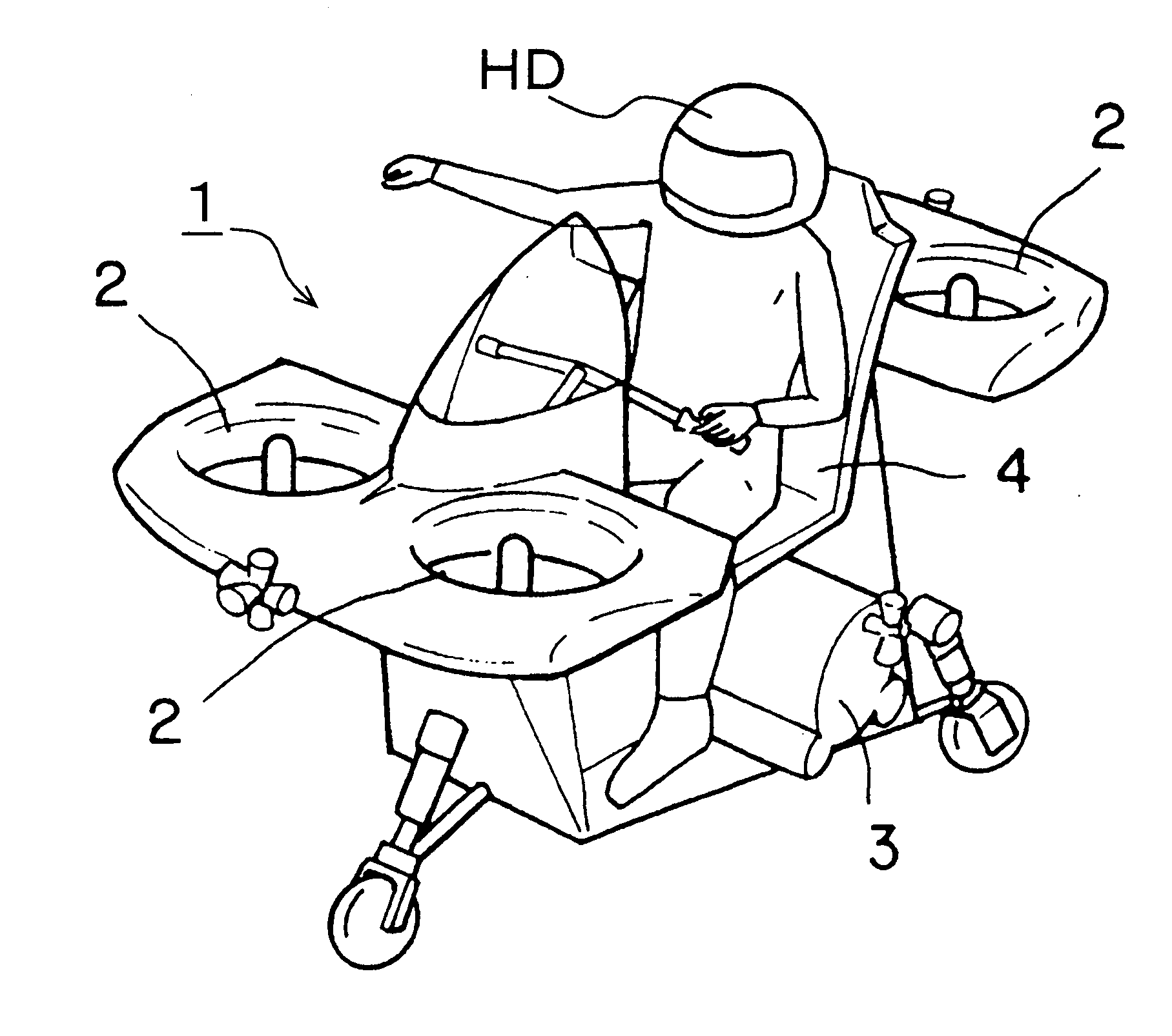
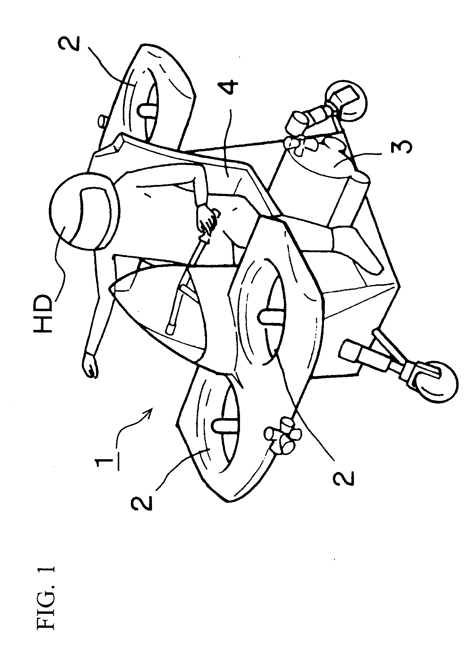
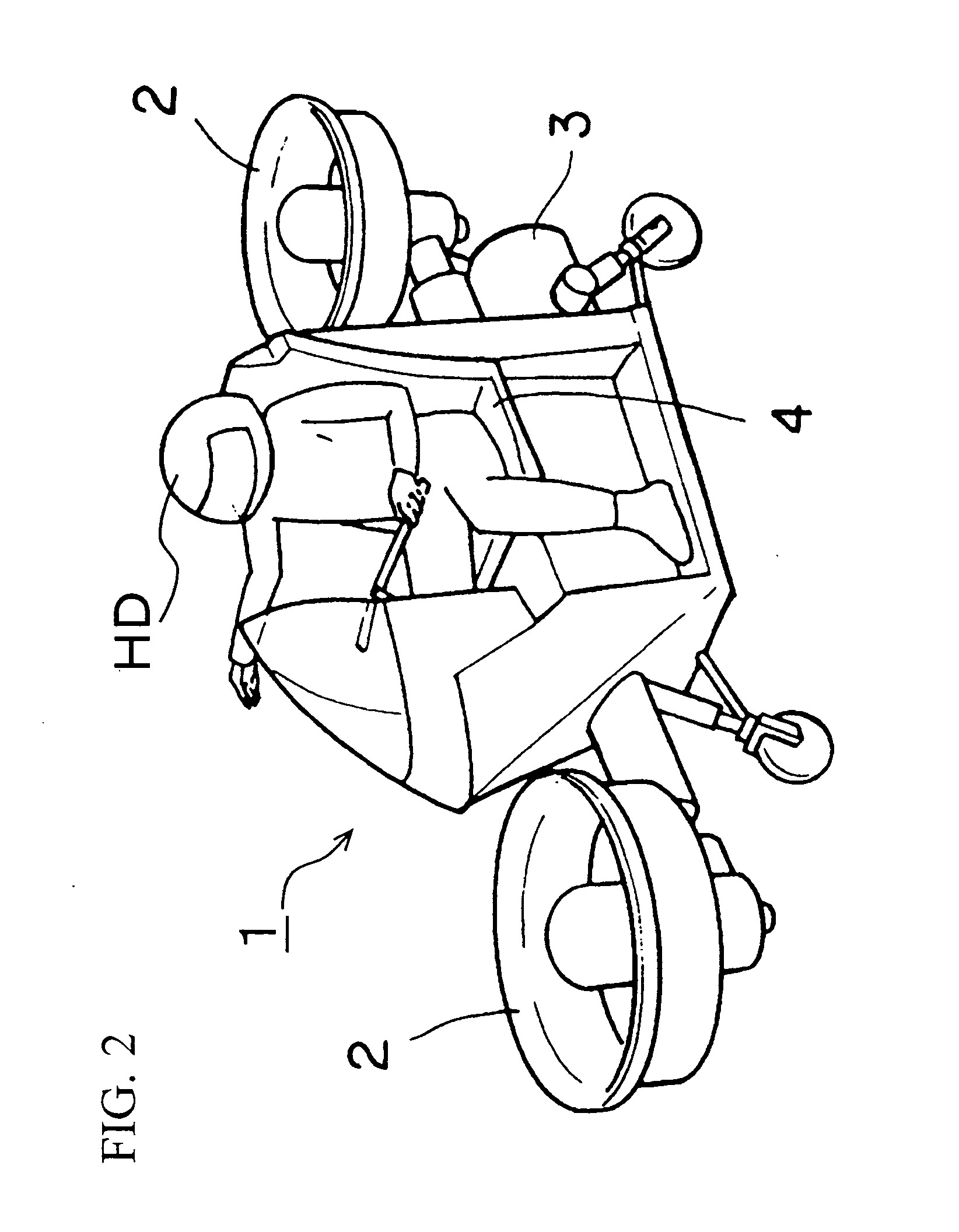
[0036] FIGS. 1 to 3 schematically show the structure of vertical take-off and landing aircrafts 1 according to the present invention. The embodiment that will be described below is to be applied to these vertical take-off and landing aircrafts 1. The vertical take-off and landing aircraft 1 shown in FIG. 1 is equipped with four tip turbine fans 2, two of which are provided in the front side of the operator HD and the other two of which are provided in the rear side of the operator HD. Compressed air used as drive source of these tip turbine fans 2 is stored in a compressed air tank 3 disposed below the operator seat 4 for the operator HD. The vertical take-off and landing aircraft 1 shown in FIG. 2 is equipped with two turbine fans 2, one of which is provided in the front side of the operator HD and the other of which is provided in the rear side of the operator HD. Compressed air used as drive source of these tip turbine fans 2 is stored in a compressed air tank 3 disposed in the r...

embodiment 2

[0041]FIG. 6 schematically shows a vertical take-off and landing aircraft according to the second embodiment. The basic structure of the vertical take-off and landing aircraft 1 shown in FIG. 6 is the same as the vertical take-off and landing aircraft shown in FIG. 1. What is different is that the tip turbine fan 2 of the vertical take-off and landing aircraft shown in FIG. 6 has two fans that is arranged in series one above the other. The rotation directions of fans in each tip turbine fan 2 are opposite to each other as indicated by solid arrows in FIG. 6. A more detailed structure of the tip turbine fan 2 of this embodiment is shown in FIG. 7. In FIG. 7, elements the same as the elements of the tip turbine fan 2 shown in FIG. 4 are designated by the same reference numerals, and detailed descriptions thereof will be omitted.

[0042] A difference between the tip turbine fan 2 shown in FIG. 7 and the tip turbine fan 2 shown in FIG. 4 resides in that the former has two fans (10a and 1...

embodiment 3

[0047]FIG. 8 shows the structure of a system related to compressed air supply in a tip turbine fan 2 of a vertical take-off and landing aircraft 1 according to this embodiment. FIG. 9 shows the structure of the tip turbine fan 2 in detail. The specific structure of the tip turbine fan 2 is the same as that shown in FIG. 7, and the same components are designated by the same reference numerals, and detailed descriptions thereof will be omitted. To facilitate description, in FIG. 9, the elements in the right side of the rotation axis SL of the main shaft 17 are designated by reference numerals to which “R” is suffixed, and the elements in the left side of the rotation axis SL are designated by reference numerals to which “L” is suffixed.

[0048] As shown in FIG. 8, the tip turbine fan 2 of this embodiment has twelve compressed air intake ports 14 leading to the turbine chamber 15. To each compressed air intake port 14, a compressed air supply passage 6 for supplying compressed air from ...


PUM


Abstract

An object of the invention is to prevent non-uniformity in the temperature distribution from occurring in a tip turbine fan in a vertical take-off and landing aircraft that uses the tip turbine fan as a source of thrust. In a vertical take-off and landing aircraft provided with a tip turbine fan in which a fan is rotated by blowing, in an annular turbine chamber provided around a rotation shaft of the fan at the center, compressed gas to a tip turbine attached to the fan to enable vertical take-off and landing, three or more compressed gas intake ports for supplying compressed gas to said turbine chamber are provided at regular intervals along the circumference of the turbine chamber.

Description

BACKGROUND OF THE INVENTION [0001] 1. Field of the Invention [0002] The present invention relates to a vertical take-off and landing aircraft that is adapted to perform vertical takeoff and landing. [0003] 2. Description of Related Art [0004] In a conventional helicopter that can take off and land vertically, thrust is controlled by collective pitch control in which the pitch angle of the main rotor is changed. In the collective pitch control, the engine speed is kept constant, and thrust is adjusted only by changing the pitch angle of the main rotor. However, a change in the pitch angle causes a change in the air resistance of the main rotor, which, in turn, causes a change in the engine load. Consequently, the engine speed may change in some cases, which sometimes leads to a change in the altitude of the helicopter. In addition, the collective pitch control requires the operator to have expertise in the operation, and it is necessary for the operator to adjust the thrust while pre...

Claims


Application Information

Patent Timeline
Patent Type & Authority Applications(United States)
IPC IPC(8): B64C29/00
CPCB64C27/20B64C39/026B64C29/0025
Inventor ISHIBA, MASATSUGU
Owner TOYOTA JIDOSHA KK
Why Eureka
Try Eureka