Non-Contact Transport Apparatus

a technology of transport apparatus and non-contact, which is applied in the direction of lighting and heating apparatus, furniture, charge manipulation, etc., can solve the problems of large negative pressure generated only at the central portions of the jetting port, difficult to secure a uniform holding force over the entire surface of the workpiece, and inability to obtain the desired product quality, etc., to achieve stable holding and transport, and simple structure

Inactive Publication Date: 2007-12-20
SMC CORP
View PDF13 Cites 58 Cited by
  • Summary
  • Abstract
  • Description
  • Claims
  • Application Information

AI Technical Summary

Benefits of technology

[0010]A general object of the present invention is to provide a non-contact transport apparatus which has a simple structure, and which makes it possible to stably hold and transport a thin large-sized workpiece in a non-contact manner.

Problems solved by technology

However, as the apparatus is large in size, it is difficult to secure a uniform holding force over the entire surface of the workpiece.
Thus, it is feared that strains may be generated on the workpiece, making it impossible to obtain a desired product quality.
However, a large negative pressure can be generated only at the central portions of the jetting ports.
As a result, the air flow passages become complicated, production costs are increased, and the apparatus consequently becomes large in size.
However, forming the curved gas guide surface requires complicated processing.
Further, the pressure distribution generated by the gas guide surface is not constant.
Therefore, it is difficult to stably hold the workpiece without causing strain and / or warpage.
When a plurality of transport heads are provided, the respective air flows that are discharged from adjoining heads collide with each other, making it impossible to generate a desired negative pressure, since air is directed radially outwardly from the transport heads.

Method used


Image

  • Non-Contact Transport Apparatus
  • Non-Contact Transport Apparatus
  • Non-Contact Transport Apparatus

Examples


first embodiment

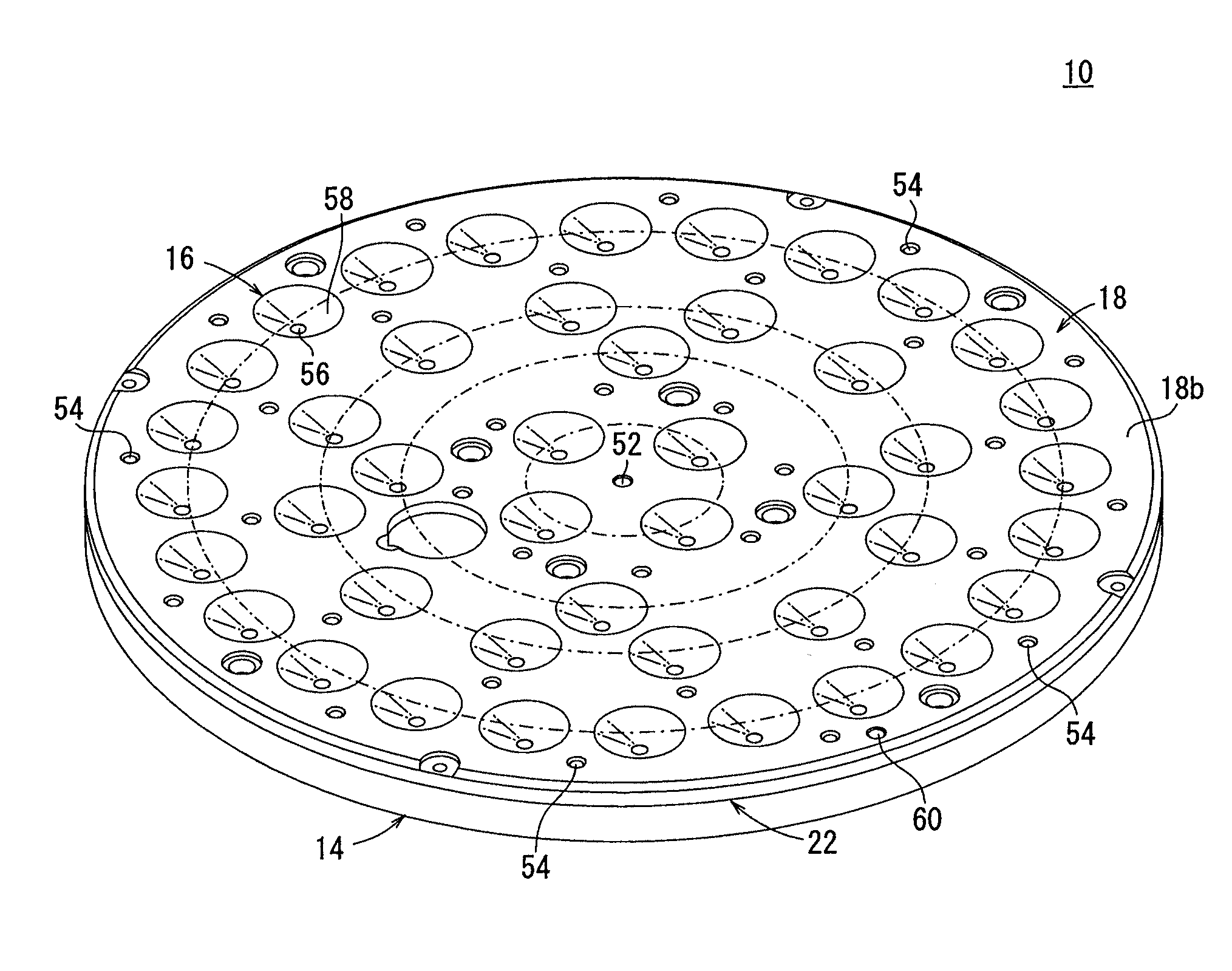
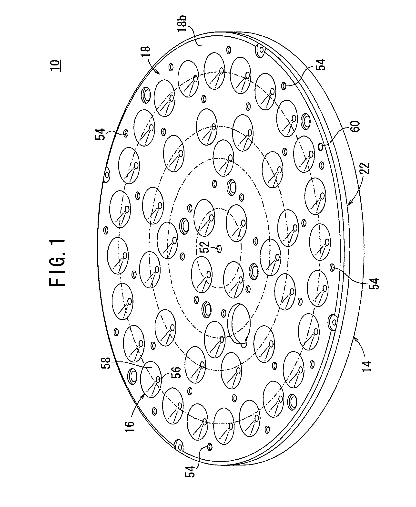
[0029]With reference to FIG. 1, reference numeral 10 indicates a non-contact transport apparatus according to the present invention.

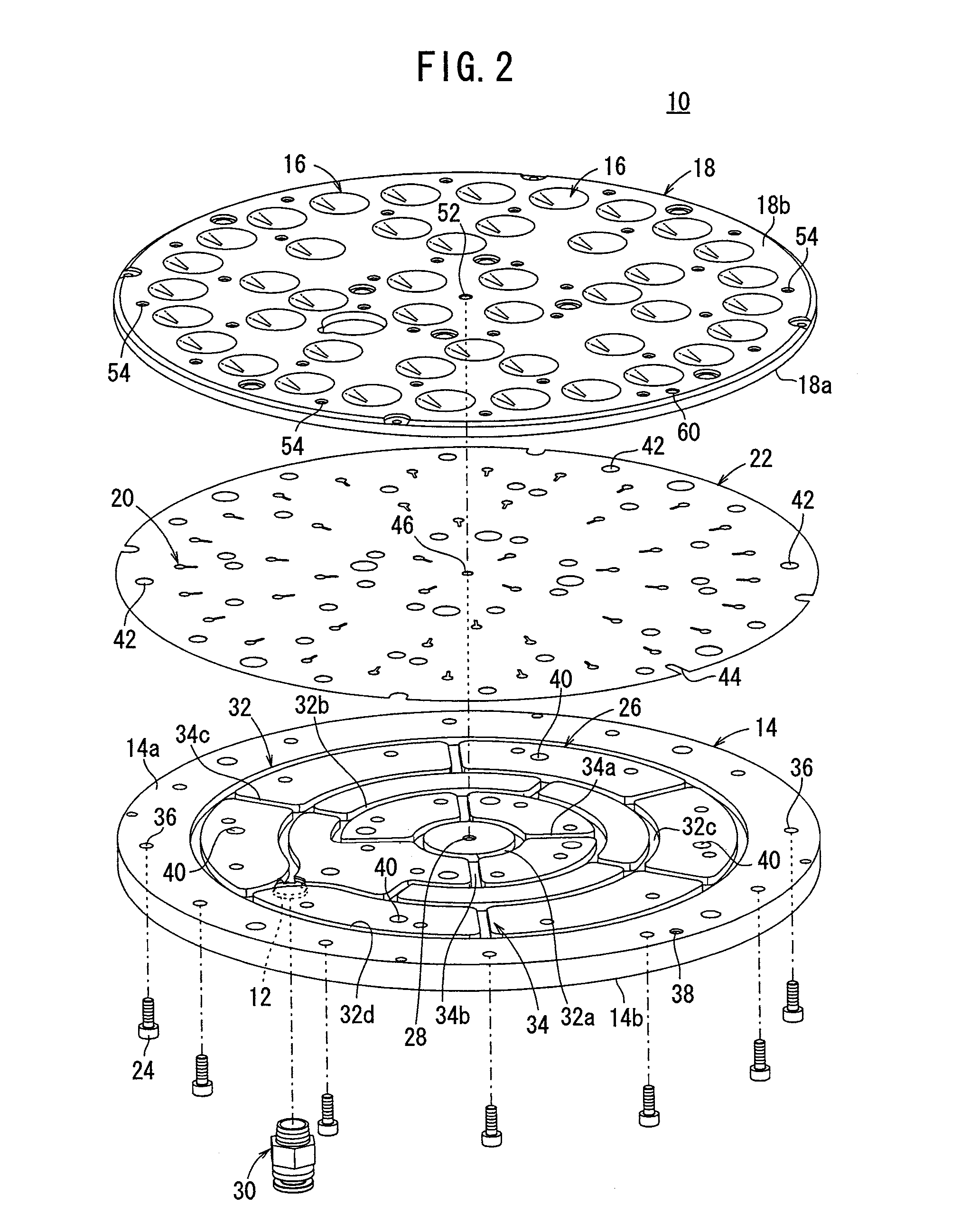
[0030]As shown in FIGS. 1 to 4, the non-contact transport apparatus 10 comprises a top plate 14 having a disk-shaped form, and which has a supply port (air supply section) 12 for supplying air thereto, a diffuser plate (under plate) 18 having a plurality of discharge holes (outlet holes) 16 for discharging air therefrom, a sheet-shaped nozzle plate (intermediate plate) 22 interposed between the top plate 14 and the diffuser plate 18, and which has a plurality of nozzles (guide passages) 20 therein, and a plurality of connecting bolts 24 that serve to fasten the stacked top plate 14, the nozzle plate 22, and the diffuser plate 18 integrally together.

[0031]The top plate 14 is formed, for example, from a resin material, or from a metal material such as an aluminum alloy. The top plate 14 is formed with flow passages 26 therein through which air flows. The ...


PUM


Abstract

A non-contact transport apparatus comprises a top plate with a supply port for supplying air thereto, a diffuser plate having a plurality of discharge holes for discharging air, and a sheet-shaped nozzle plate interposed between the top plate and the diffuser plate and having a plurality of nozzles therein. The top plate, the nozzle plate and the diffuser plate are stacked and integrally connected to one another through a plurality of connecting bolts. Air is supplied from the supply port and via flow passages to the plurality of nozzles. Air is directed to the outside from the plurality of discharge holes, via radially formed nozzles oriented in a radially outward direction.

Description

BACKGROUND OF THE INVENTION[0001]1. Field of the Invention[0002]The present invention relates to a non-contact transport apparatus capable of holding and transporting a workpiece in a non-contact state.[0003]2. Description of the Related Art[0004]A non-contact transport apparatus has hitherto been known, which is capable of transporting a semiconductor wafer or other workpiece in a non-contact manner utilizing the Bernoulli effect generated by the flow of a gas. The workpiece may be composed of a sheet-shaped part for constructing a display device, such as a liquid crystal or a plasma display.[0005]For example, as disclosed in Japanese Laid-Open Patent Publication No. 2002-64130, such a non-contact transport apparatus includes, for example, a recess having an inner circumferential surface with a circumferential shape, a flat surface formed on a side of an opening of the recess which is opposed to a workpiece, and a fluid passage that discharges a supply fluid into the recess by mean...

Claims


Application Information

Patent Timeline
Patent Type & Authority Applications(United States)
IPC IPC(8): B65H29/00B65G49/07
CPCH01L21/6838H01L21/67784B65G49/065B65G51/02B65G2203/0233
Inventor NAGAI, SHIGEKAZUSAITOH, AKIOSOMEYA, MASAHIKOSAITOH, MASARUYOSHIDA, YUKIHISA
Owner SMC CORP
Why Eureka
Try Eureka