Electronic volume apparatus

Inactive Publication Date: 2007-12-20
ROHM CO LTD
View PDF3 Cites 2 Cited by
  • Summary
  • Abstract
  • Description
  • Claims
  • Application Information

AI Technical Summary

Benefits of technology

[0010]The present invention has been made in consideration of the above problems, and a general purpose of the present invention is to provide an electronic volume apparatus which can switch volumes while suppressing noise from being generated.

Problems solved by technology

For this reason, the signal component causes noise to be generated.

Method used


Image

  • Electronic volume apparatus
  • Electronic volume apparatus
  • Electronic volume apparatus

Examples


first setting example

[0062]In a first setting example, as the control function g(t), the target function f(t) itself is defined. In this case, in the digital control unit 32 in FIG. 4, a trigonometric function may be calculated as a function of time t, and a digital value DIG may be output. A storing means such as a resistor may be arranged in the digital control unit 32 to record the time t and the value of the trigonometric function in association with each other, and the values may be read in each case.

second setting example

[0063]In a second setting example, as the control function g(t), a function by quantizing the target function f(t) is defined. The target function f(t) is divided by N (N is an integer which is not less than three) in a range of time t=0 to t=Tp. A division point obtained by the division is linearly interpolated.

[0064]FIG. 6 is a waveform chart showing the control function g(t) obtained by quantizing the target function f(t) in FIG. 5. The control function g(t) in FIG. 6 is obtained when N=5 is satisfied. A range of g1 to g2 along a vertical axis of the target function f(t) is equally divided by N=5 in a direction of a dependent variable. The control function g(t) is a function obtained by linearly interpolating division points p0 to p5 obtained as described above.


PUM


Abstract

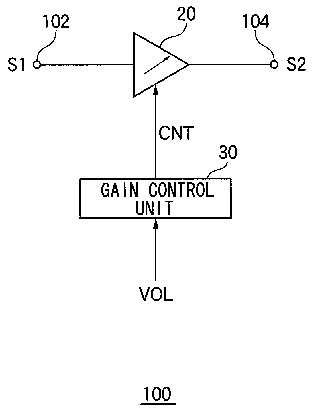
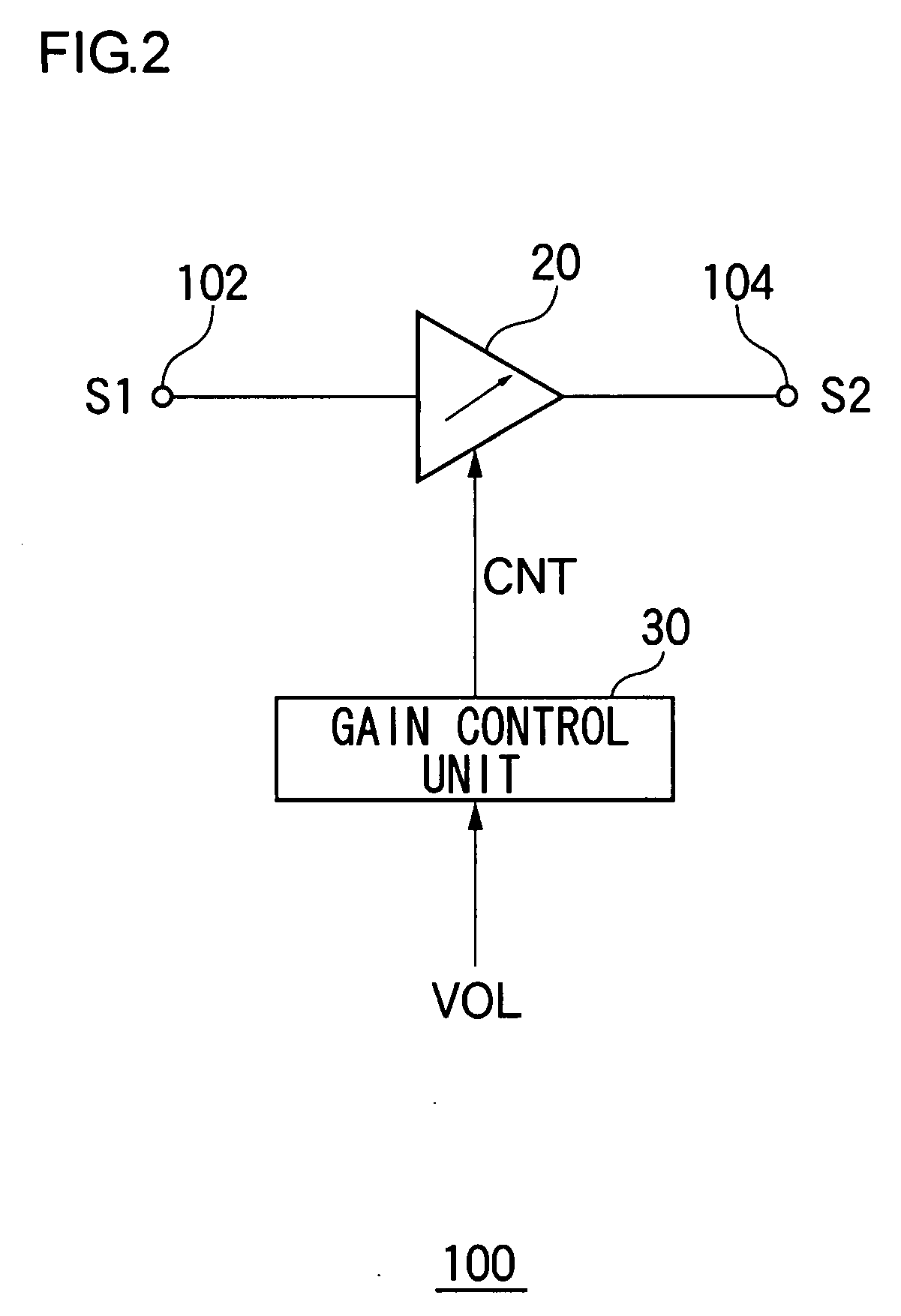
In an electronic volume apparatus, a gain having an initial value g1 at time t=0 in an initial state is transited to a target value g2 at time t=Tp after a certain transition period Tp elapses. A gain control unit controls the gain of the amplifier depending on a control function g(t) which satisfies the following conditions (1) to (3):g(0)=g1, g(Tp)=g2;   (1)g′(Tp / 2)>g′(0); and   (2)g′(Tp / 2)>g′(Tp).   (3)where g′(t) is time differentiation of g(t).

Description

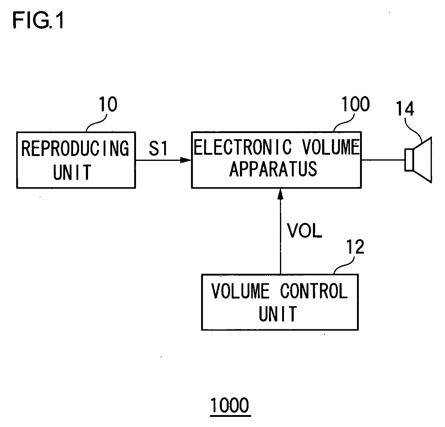
BACKGROUND OF THE INVENTION[0001]1. Field of the Invention[0002]The present invention relates to an electronic volume apparatus which controls a volume of an audio signal.[0003]2. Description of the Related Art[0004]An electronic device such as a CD player, an audio amplifier, a car stereo system, or a portable radio and portable audio player having a function of reproducing an audio signal generally includes a volume controller which adjusts a volume, an equalizer which adjusts frequency characteristics, and the like. The volume controller and the equalizer are controlled by changing an amplitude of an audio signal.[0005]An audio signal is amplified by an amplifier and finally output as sound from a loudspeaker or headphones which is a sound output means. Volume adjustment is realized by controlling a gain of an amplifier or controlling a rate of decrease of an attenuator. For example, Japanese Patent Application Laid-open Nos. 2005-117489 and 2005-217710 disclose an electronic vol...

Claims


Application Information

Patent Timeline
IPC IPC(8): H03G3/10
CPCH03G3/001
Inventor SAKAI, MITSUTERUSATO, YOSUKE
Owner ROHM CO LTD
Why Eureka
Try Eureka