
Implant and delivery system with multiple marker interlocks

a delivery system and implant technology, applied in the field of vascular implant delivery systems, can solve the problems of stent premature deployment, large expansile force, dislocation of stents, etc., and achieve the effects of reducing the deployment force of implants, reducing the constrained diameter of implants, and reducing the length of implant constraints

Active Publication Date: 2007-12-20
TYCO HEALTHCARE GRP LP
View PDF7 Cites 68 Cited by
  • Summary
  • Abstract
  • Description
  • Claims
  • Application Information

AI Technical Summary

Benefits of technology

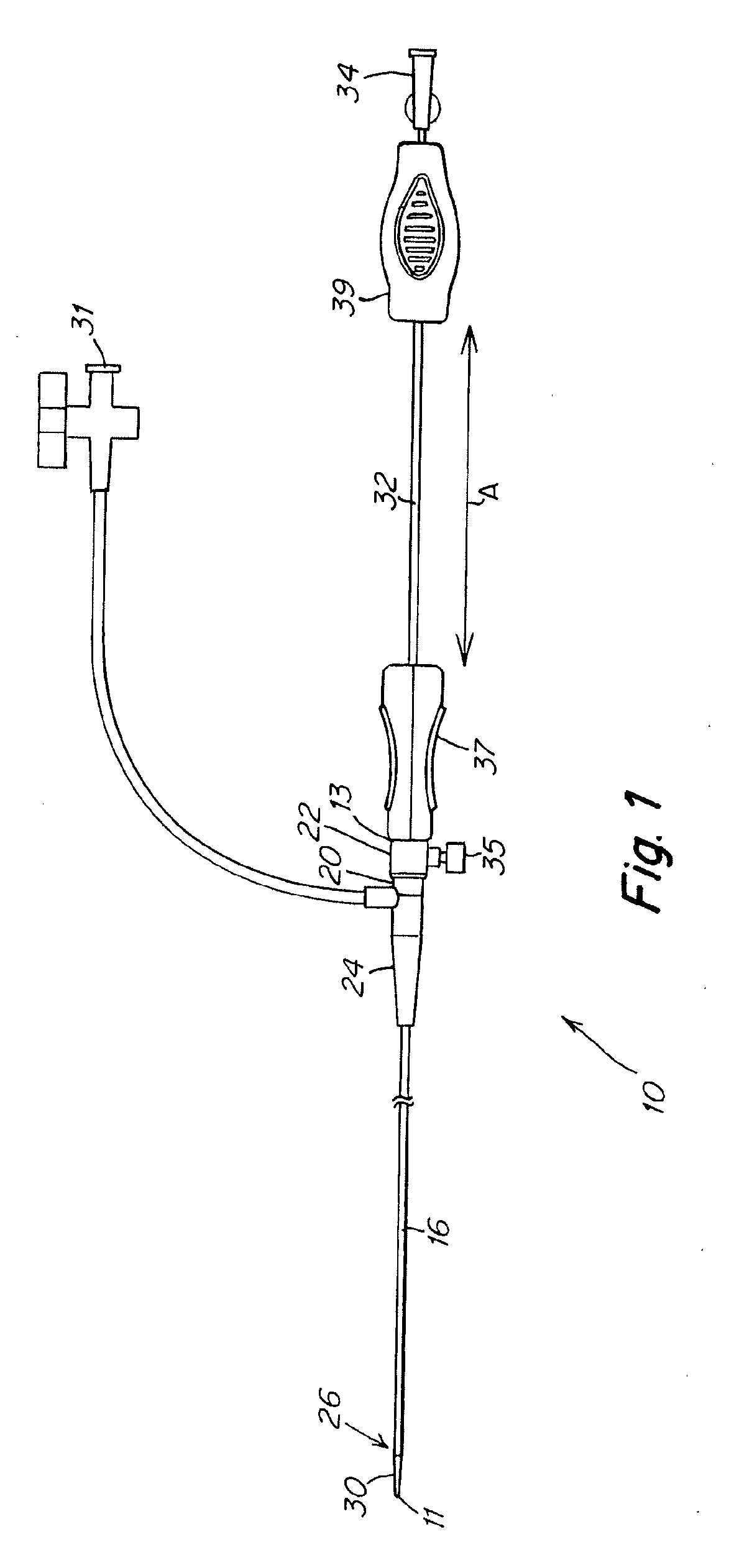
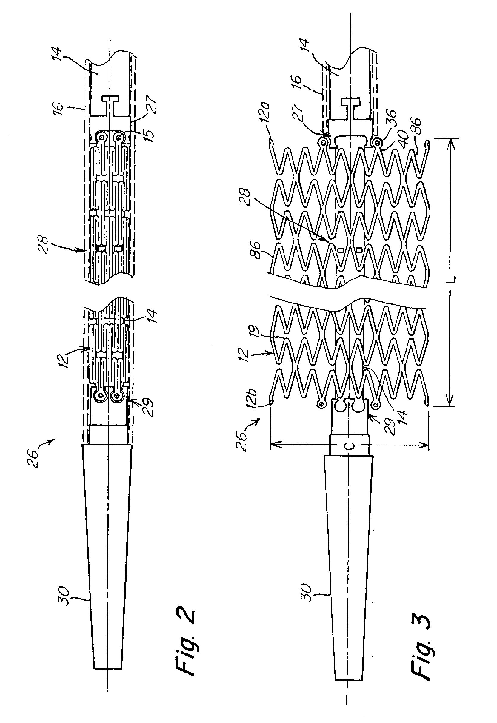
[0012] An implant delivery system comprises one or more interlock assemblies which connect the implant delivery catheter to the implant, an improved inner tubular member and an outer tubular member. A distal interlock assembly prevents axial movement of the implant relative to the inner member during deployment. The improved inner tubular member is reinforced or made of a material which is able to resist inward radial compressive forces thereon from the implant during deployment of the implant. The implant is frictionally engaged against the inner surface of the outer tubular member prior to deployment and as the outer tubular member is withdrawn proximally during deployment. The interlock assemblies, improved inner tubular member and outer tubular member cooperate to place the implant in tension during deployment, resulting in a decrease in the constrained diameter of the implant during deployment and a lengthening of the constraint length of the implant thereby reducing implant deployment force. A proximal interlock assembly accommodates any increases in the constrained length of the implant at the proximal end thereof which accompany decreases in the constrained diameter of the implant caused by the tensioning of the implant during deployment.

Problems solved by technology

This is especially true when attempting to deploy, for example, long devices, devices with a large amount of expansile force when compressed in a sheath, or bulky devices compressed into small sheaths in tortuous vessels.
In addition, in prior art devices, the stent may prematurely deploy as the outer tube is retracted.
This can result in the stent being propelled distally beyond a desired deployment site.
Also, once the stent is partially unsheathed, it is sometimes determined that the stent placement needs to be adjusted.
With some existing systems, this is difficult since the stent has a tendency to force itself out of the sheath thereby making adjustments difficult.
Further, once the stent has been deployed, subsequent adjustment of the stent deployment location can be difficult because re-sheathing typically cannot be readily accomplished.
While interlocks on stents and stent delivery systems have improved the precision with which some stents can be delivered to treatment sites, it has been found that certain types of stents are not effectively delivered even by the existing interlock systems.
Stents with high axial flexibility parallel to the central axis of the stent can also be very difficult to deploy, and to deploy precisely, with the existing interlock systems.
Visualization of these stents during deployment, particularly of the long stents, is often inadequate.
These types of stents can also be difficult to load into the stent delivery system as well.

Method used


Image

  • Implant and delivery system with multiple marker interlocks
  • Implant and delivery system with multiple marker interlocks
  • Implant and delivery system with multiple marker interlocks

Examples


example 1

[0071] Stents 6 mm in diameter and 150 mm or 200 mm long and having structures similar to that shown in FIG. 5A were laser cut from binary nitinol alloy tubing, expanded, and heat treated using processes known in the art. Stents (150 mm long or 200 mm long) were mounted on prior art Stent Delivery Systems (SDS) and stents (200 mm long) were mounted on inventive SDS. Aside from differences associated with stent length, inventive SDS were identical to prior art SDS except that 1) distal interlocks were present on inventive SDS and absent on prior art SDS, and 2) inventive SDS were comprised of proximal pushers while prior art SDS were comprised of proximal retainers, and 3) inventive SDS were comprised of improved inner members while prior art SDS were comprised of prior art inner members. Improved inner members (0.380″ inside diameter×0.045″ outside diameter) were comprised of 0.001″ thick polyimide inner layer, 0.0015″ thick nylon 12 outer layer and 16 braided type 304V stainless st...


PUM


Abstract

An implant delivery system has one or more interlock assemblies which connect the implant delivery catheter to the implant, an improved inner tubular member and an outer tubular member. The interlock assemblies, improved inner tubular member and outer tubular member cooperate to place the implant in tension during deployment, thereby reducing implant deployment force.

Description

FIELD OF THE INVENTION [0001] The present invention relates to a system for delivering an implant to a site in a body lumen. More particularly, this invention pertains to a delivery system for a vascular implant such as a self-expanding stent. BACKGROUND OF THE INVENTION [0002] Stents are widely used for supporting a lumen structure in a patient's body. For example, a stent may be used to maintain patency of a carotid artery, coronary artery, other blood vessel or other body lumen such as the ureter, urethra, bronchus, esophagus, or other passage. A stent is typically a metal, tubular structure, although polymer stents are known. Stents can be permanent enduring implants, or can be bioabsorbable at least in part. Bioabsorbable stents can be polymeric, bio-polymeric, ceramic, bio-ceramic, metallic, or other materials and stents may elute over time substances such as drugs. [0003] In certain stent designs, the stent is an open-celled tube that is expanded by an inflatable balloon at t...

Claims


Application Information

Patent Timeline
IPC IPC(8): A61F2/06
CPCA61F2/91A61F2/915A61F2/95A61F2002/91541A61F2002/91558A61F2230/0054A61F2002/9665A61F2250/0098A61F2220/005A61F2220/0058A61F2002/91591A61F2/966A61F2/9522
Inventor WANG, LIXIAOMA, JIANLUTATALOVICH, JOEWALTZ, PEGGYSMYTHE, KEITHKUSLEIKA, RICH
Owner TYCO HEALTHCARE GRP LP
Learn More