Heat pipe type heat dissipation device

a heat dissipation device and heat sink technology, which is applied in the direction of air heaters, indirect heat exchangers, light and heating apparatus, etc., can solve the problems of no longer meeting the heat dissipation requirements of highly heat-generating ic packages, and the heat sink is heated

Inactive Publication Date: 2007-12-27
HON HAI PRECISION IND CO LTD +1
View PDF10 Cites 10 Cited by
  • Summary
  • Abstract
  • Description
  • Claims
  • Application Information

AI Technical Summary

Benefits of technology

[0003]U.S. Pat. No. 5,699,853 discloses a typical heat pipe type heat dissipation device. The heat dissipation device is provided with two spaced and parallel base plates, a plurality of fins sandwiched between the base plates and some heat pipes connecting the two base plates. During operation, one of the base plate is held in contact with an operating electronic component to absorb heat and transfer it to the fins, to the heat pipe, and then to the other base plate and the fins for dissipation. In this heat dissipation device, the base plate contacting the electronic device has its hot middle portion closer to electronic component than other portions thereof. The heat absorbed from the electronic component is first accumulated in the middle portion of the base plate, then spreads around the base, and is then conducted to the fins directly or by the heat pipes. It can be seen that facilitating heat transfer from this hot region of the base plate to others and decreasing heat density thereof as fast as possible is an important problem which needs addressing. If this hot area of the base plate can be cooled efficiently, the heat dissipation performance of the whole assembly will be enhanced; therefore, further optimization of the heat dissipation device is desirable.

Problems solved by technology

However, as the operating speed of electronic components has increased markedly in recent years, such a conventional heat sink, which transfers heat solely by metal conduction, can no longer meet the heat dissipation requirements of highly heat-generating IC packages.
It can be seen that facilitating heat transfer from this hot region of the base plate to others and decreasing heat density thereof as fast as possible is an important problem which needs addressing.

Method used


Image

  • Heat pipe type heat dissipation device
  • Heat pipe type heat dissipation device
  • Heat pipe type heat dissipation device

Examples


Embodiment Construction

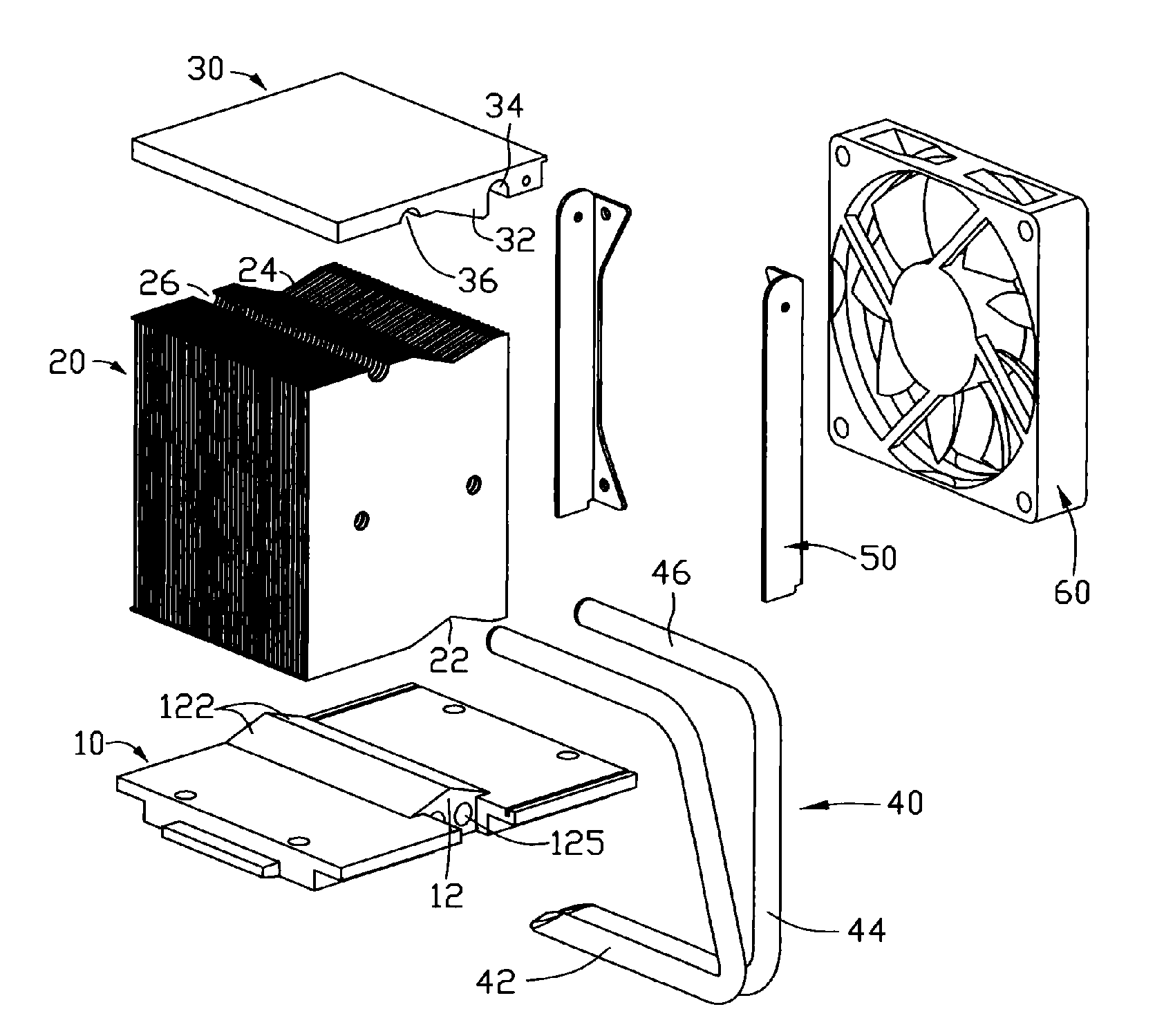
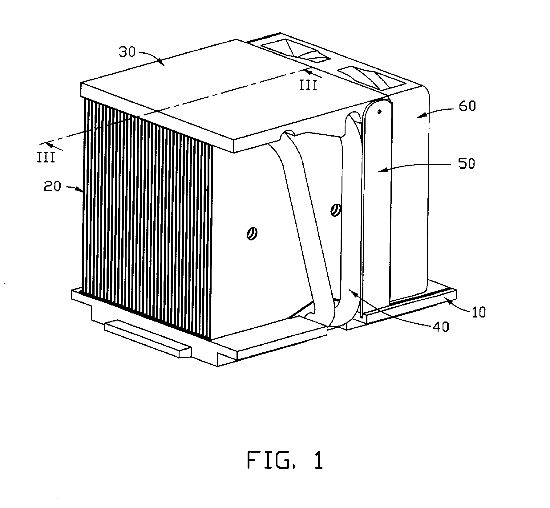
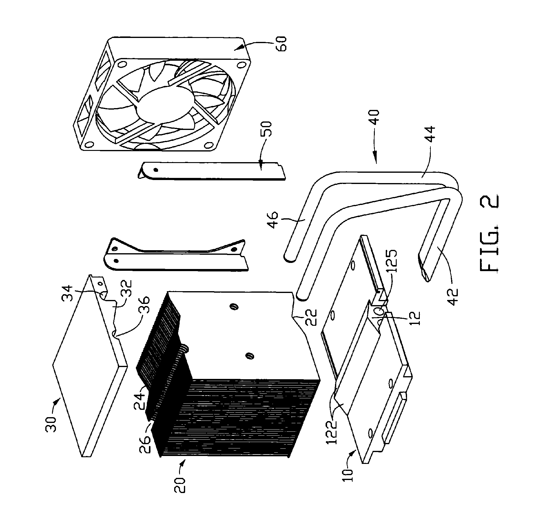
[0011]Referring to FIG. 1, a heat pipe type heat dissipation device in accordance with a preferred embodiment of the present invention is used for dissipating heat from an electronic component, such as an integrated circuit package (not shown). The heat dissipation device comprises a base plate 10, a cover plate 30 spaced from the base plate 10, two heat pipes 40 connecting the cover plate 30 and the base plate 10, and a plurality of parallel fins 20 extending between the base plate 10 and cover plate 30 and connecting with them.

[0012]The base plate 10 has a planar and smooth bottom face for contacting the electronic component and a top face opposite to the bottom face.

[0013]The cover plate 30 is separately located above and parallel to the base plate 10, having a planar and smooth top face and bottom face facing towards the base plate 10.

[0014]The fins 20 are arranged between the base plate 10 and the cover plate 30 and in connection with them. The fins 20 are arrayed parallel to e...


PUM


Abstract

A heat pipe type heat dissipation device for an electronic component comprises a base plate, a cover plate spaced from the base plate, a plurality of parallel fins extending between the base plate and the cover plate and connecting with them. The base plate, the cover plate and each two adjacent fins collectively define a unitary air passage. The base plate has a protuberant portion, which has a convex surface facing towards the cover plate and has a thickness getting small from the middle to two sides in a direction parallel to the fins. The cover plate also has a protuberant portion similar to the protuberant portion of the base plate. A heat pipe connects the protuberant portions of the cover plate and the base plate.

Description

1. FIELD OF THE INVENTION[0001]The present invention generally relates to heat dissipation devices, and more particularly to a heat pipe type heat dissipation device for cooling an electronic component, such as an integrated circuit package.2. DESCRIPTION OF RELATED ART[0002]Electronic components, such as central processing units (CPUs) include numerous circuits operating at high speed and generate substantial heat. Under most circumstances, it is necessary to cool the components in order to maintain safe operating conditions and assure that the components function properly and reliably. In the past, various approaches have been used to cool electronic components. A common approach is to mount a finned metal heat sink on top of the component. A conventional finned metal heat sink is made of highly heat-conductive metal, such as copper or aluminum, and generally includes a base for contacting the electronic component to absorb heat therefrom and a plurality of fins formed on the base...

Claims


Application Information

Patent Timeline
Patent Type & Authority Applications(United States)
IPC IPC(8): H05K7/20
CPCH01L23/3672H01L23/427H01L23/467H01L2924/0002H01L2924/00
Inventor XIA, WAN-LINZHONG, YONGLONG, JUN
Owner HON HAI PRECISION IND CO LTD
Why Eureka
Try Eureka