Water circulation systems for ponds, lakes, municipal tanks, and other bodies of water

a technology for municipal tanks and water bodies, applied in water cleaning, sustainable biological treatment, biological water/sewage treatment, etc., can solve the problems of large volume of water in the hose not being able to quickly escape out of the restricted bottom or inlet of the hose, and affecting the efficiency of the system. , to achieve the effect of effectively bringing chlorine, preventing or at least inhibiting their return, and relatively quick manner

Active Publication Date: 2007-12-27
IXOM OPERATIONS
View PDF24 Cites 17 Cited by
  • Summary
  • Abstract
  • Description
  • Claims
  • Application Information

AI Technical Summary

Benefits of technology

[0014] Another aspect of the present inventions for bodies of water that may develop large and violent waves includes adaptations to the floats for the elongated arms of the platform. In this regard, the floats are mounted to the ends of the arms so as to be substantially free to move essentially universally relative to the arms. The floats extend above rather than below the ends of the arms and are connected by flexible arrangements such as chains, cables, ropes, and ball joints. Violent waves or forces in the water can then press sideways against and move the floats without creating damaging forces or torques on the arms.
[0015] Still other improvements of the present invention serve to particularly adapt the circulation system to municipal and similar tanks or containers for drinking or potable water. Such systems have specific needs and requirements. Among them, the system needs to thoroughly mix the water in a relatively quick and sustainable manner to

Problems solved by technology

However, a problem can occur that the large volume of water in the hose cannot quickly escape back out of the restricted bottom or inlet of the hose as it is lifted with a wave.
Consequently, great stresses are put on the flotation platform and hose of the system as the flotation platform rises with each wave and attempts to pull up with it the very heavy hose full of water.
In extreme cases, the stresses can damage or even destroy the flotation platform as well as the hose and other parts of the system.
As indicated above, the primary cause of the problem in such systems is that the column of water in the hose cannot escape fast enough out the restricted bottom of the

Method used


Image

  • Water circulation systems for ponds, lakes, municipal tanks, and other bodies of water
  • Water circulation systems for ponds, lakes, municipal tanks, and other bodies of water
  • Water circulation systems for ponds, lakes, municipal tanks, and other bodies of water

Examples


Embodiment Construction

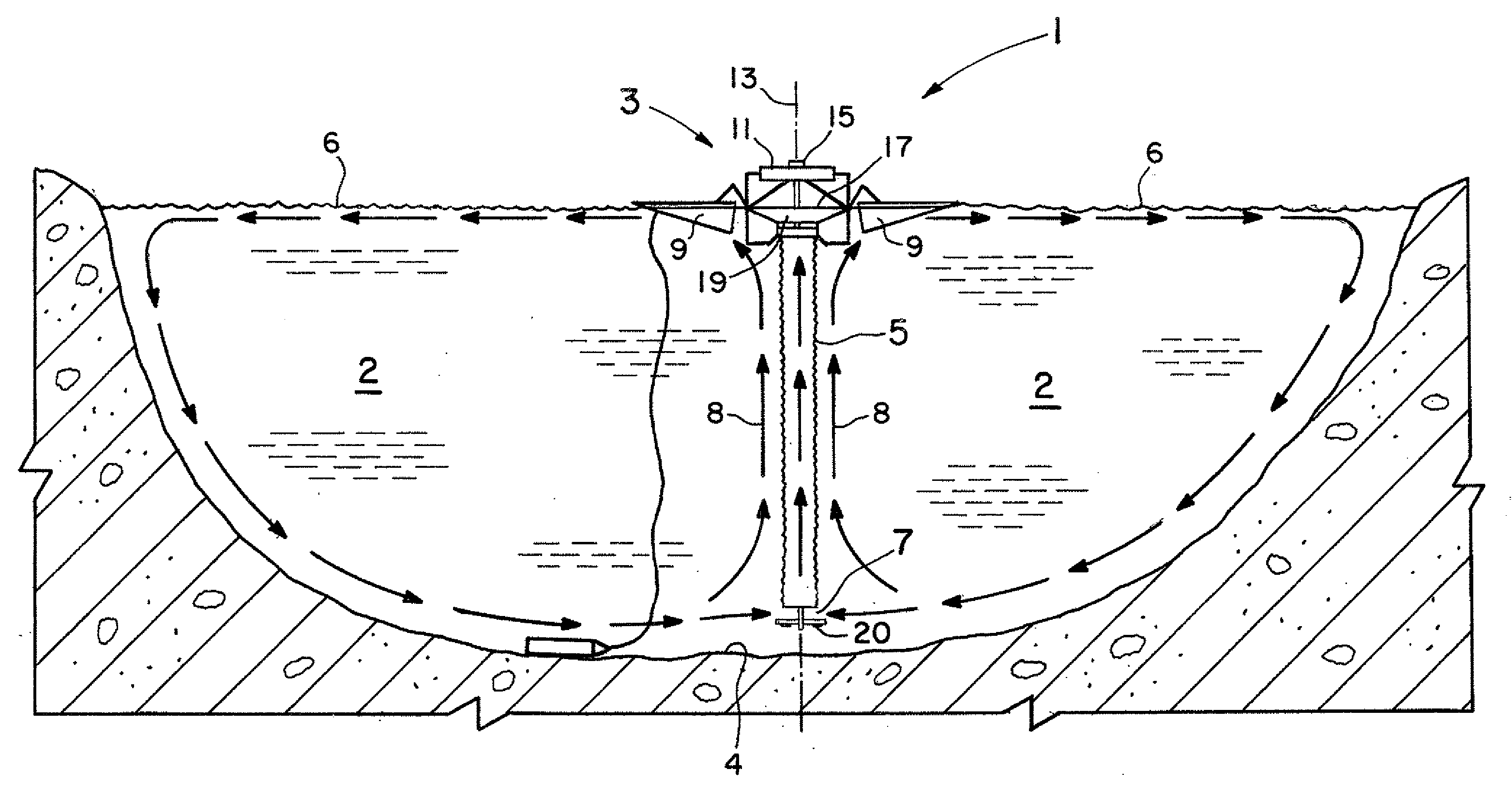
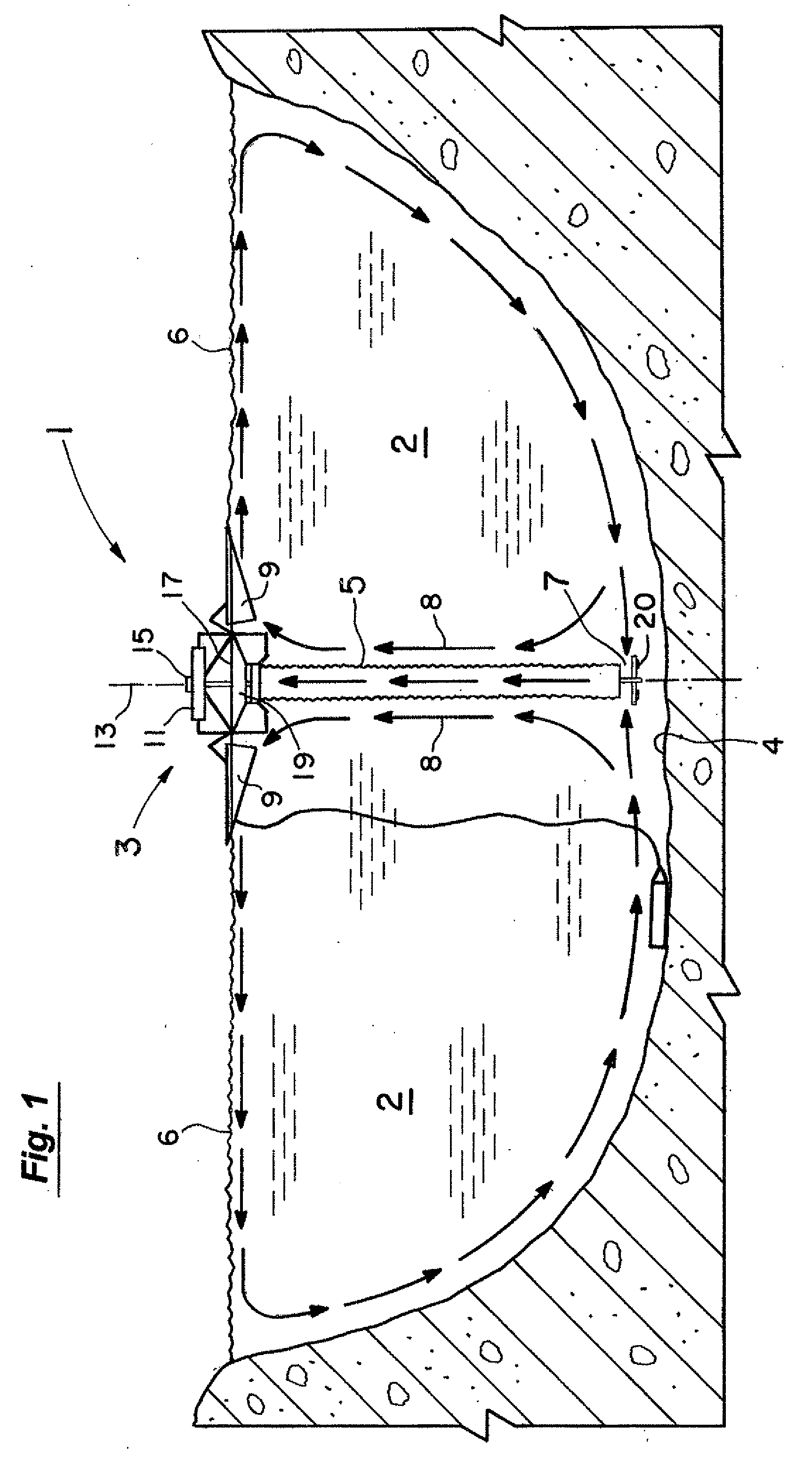
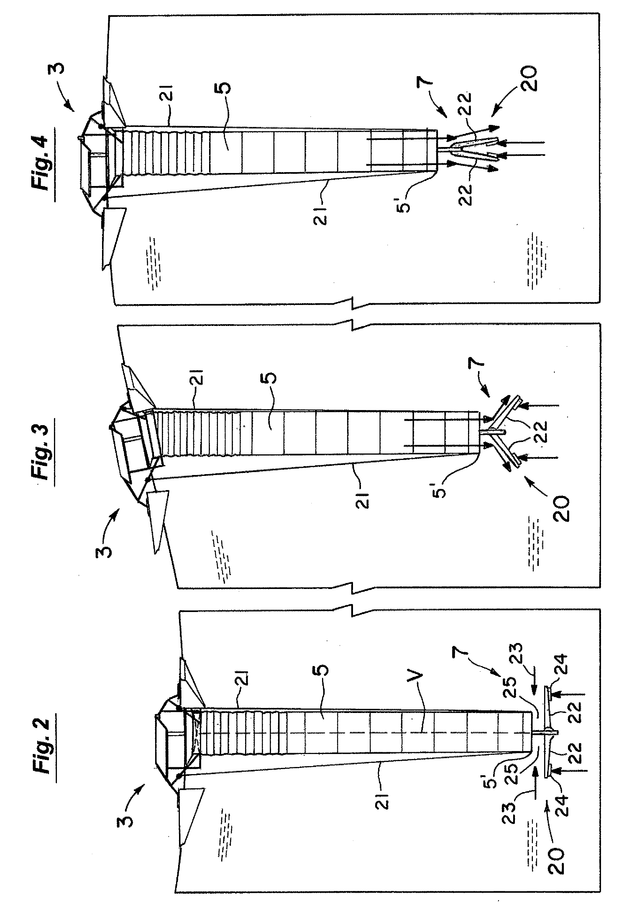
[0034] As schematically shown in FIGS. 1, the water circulation system 1 of the present invention for large bodies of water such as a pond or lake 2 includes an upper flotation platform or floating portion 3 with a draft hose or tube 5 depending downwardly from the platform 3 toward the lake bottom 4 to the water inlet 7 to the hose 5. The flotation platform 3 includes a plurality of floats 9 (e.g., three) supported thereon. The floats 9 extend outwardly of the central axis 13 (FIG. 1) of the platform 3 and are preferably evenly spaced thereabout. The floats 9 extend far enough out from the central axis 13 to provide a relatively stable and buoyant support structure for the system 1 including its solar panels 11, electric motor 15, dish 17, and impeller at 19 as well as for the depending draft hose 5 and the structure of the water inlet 7. One or more cables or lines 21 as in FIGS. 2-4 can also be provided to extend from the flotation platform 3 down to the bottom portion 5′ of the ...


PUM

PropertyMeasurementUnit
Lengthaaaaaaaaaa
Angleaaaaaaaaaa
Lengthaaaaaaaaaa

Abstract

A circulation system for bodies of water. In one set of embodiments for larger bodies of water, modified horizontal plate designs are provided at the entrance of the draft hose. The plate designs have sections that pivot downwardly as the flotation platform and depending draft hose are rapidly raised in high wave conditions to let the water escape downwardly out of the hose. Adaptations to the floats for the elongated arms of the platform are also made to essentially eliminate the creation of any damaging torques on them from high waves. Another set of embodiments are particularly adapted for smaller systems in municipal water tanks for thorough mixing of the water and treatment to kill undesirable ammonia oxidizing bacteria and prevent or at least inhibit their return.

Description

RELATED APPLICATIONS [0001] This application claims the benefit of U.S. Provisional Patent Application Ser. No. 60 / 791,091 filed Apr. 10, 2006, which application is incorporated herein by reference.BACKGROUND OF THE INVENTION [0002] 1. Field of the Invention [0003] This invention relates to the field of circulation systems for ponds, lakes, municipal tanks, and other bodies of water. It particularly relates to the field of such circulation systems for relatively large and deep bodies of water in which high waves may periodically develop. It also relates to circulation systems for smaller and shallower bodies of water such as in municipal or similar water tanks and containers. [0004] 2. Discussion of the Background [0005] One group of improvements of the present invention has particular application to larger and deeper bodies of water that may develop large waves (e.g., 4-6 feet high or more). Circulation systems for such bodies that float on the surface of the water must then rise v...

Claims


Application Information

Patent Timeline
IPC IPC(8): C02F1/00C02F1/68C02F1/76B01F27/91
CPCB01F3/04609B01F3/04773E02B1/003C02F1/76C02F7/00B01F13/0049E02B1/00B01F23/23341B01F23/23421B01F33/503Y02W10/37Y10T137/7898Y10T137/7839Y02W10/10C02F3/16C02F3/22B01F25/50B01F27/91
Inventor TORMASCHY, WILLARD R.KUDRNA, GARY A.OBRITSCH, TAIT J.SIMNIONIW, COREY M.BLETH, JOEL J.WEBER, LAWRENCE JOHNZENT, JONATHAN L.CRAIL, RONALD J.
Owner IXOM OPERATIONS
Why Eureka
Try Eureka