Image Processing Device, Image Processing System, Image Processing Method, Computer Program, and Semiconductor Device

a technology of image processing and frame memory, which is applied in the direction of static indicating devices, cathode-ray tube indicators, instruments, etc., can solve the problems of increased latency, inability to carry out asynchronous drawing to frame memory, and inability to provide display memory with double buffer structure, etc., to achieve the effect of increasing the amount of display memory and shortening the latency

Active Publication Date: 2007-12-27
SONY COMPUTER ENTERTAINMENT INC
View PDF6 Cites 5 Cited by
  • Summary
  • Abstract
  • Description
  • Claims
  • Application Information

AI Technical Summary

Benefits of technology

[0006] Accordingly, an object of the present invention is to solve the above-mentioned problems and to provide an image processing technique which shortens latency more than the conventional method employing the double-buffer structu

Problems solved by technology

Therefore, drawing to the frame memory cannot be carried out asynchronously with the output.
However, it is not economical to provide the display memory with the double-buffer

Method used


Image

  • Image Processing Device, Image Processing System, Image Processing Method, Computer Program, and Semiconductor Device
  • Image Processing Device, Image Processing System, Image Processing Method, Computer Program, and Semiconductor Device
  • Image Processing Device, Image Processing System, Image Processing Method, Computer Program, and Semiconductor Device

Examples


first embodiment

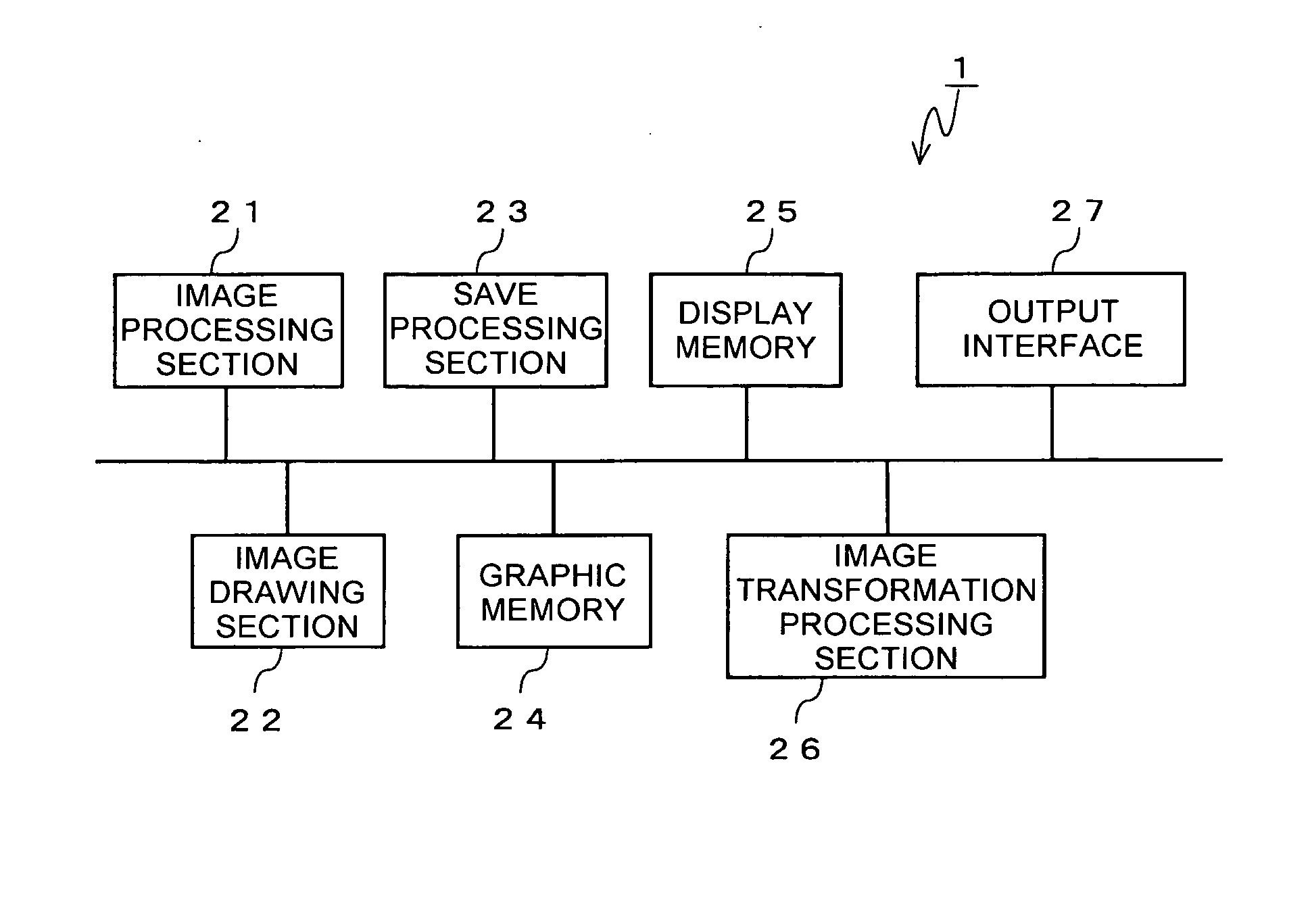
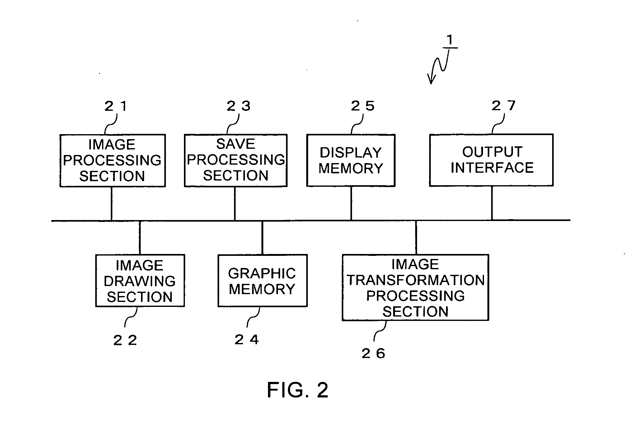
[0069] In FIGS. 4(a) to 4(d), the display memory 25 has four buffer areas so as to be able to store four pieces of partial data (one piece of frame data).

[0070] In FIG. 4(a), a second frame data is stored in the graphic memory 24 and a quadrisected first frame data is saved and stored in the display memory 25. When pieces of partial data 1-1 through 1-3 are outputted sequentially from the display memory 25 via the output interface 27 (FIG. 4(b)), the save processing section 23 saves the pieces of partial data 2-1 through 2-3 obtained by equally dividing the second frame data from the graphic memory 24 to the display memory 25 after confirming that the partial data 1-3 has been outputted. While the pieces of partial data 2-1 through 2-3 are saved, the partial data 1-4 is outputted from the display memory 25 via the output interface 27 in succession to the output of the partial data 1-3 (FIG. 4(c)). When the partial data 1-4 has been outputted, the partial data 2-4 is saved from the ...

second embodiment

[0072] In FIGS. 5(a) to 5(c), the display memory 25 has five buffer areas so as to be able to store five pieces of partial data.

[0073] In FIG. 5(a), a second frame data is stored in the graphic memory 24 and a quadrisected first frame data is saved and stored in the display memory 25. When pieces of partial data 1-1 through 1-3 are outputted sequentially from the display memory 25 via the output interface 27 (FIG. 5(b)), the save processing section 23 saves pieces of partial data 2-1 through 2-4 obtained by equally dividing the second frame data from the graphic memory 24 to the display memory 25 after confirming that the partial data 1-3 has been outputted. At the same time, the save processing section 23 causes the display memory 25 to output the partial data 1-4 (FIG. 5(c)). Because the display memory 25 can store five pieces of partial data, the display memory 25 can save all of the second frame data at once regardless of whether the partial data 1-4 is being outputted.

[0074] ...

third embodiment

[0077] In FIGS. 6(a) to 6(d), the display memory 25 has five buffer areas so as to be capable of storing five pieces of partial data. The display memory 25 is a memory that allows an in-place transformation process and is arranged so as to be capable of writing partial data after the transformation process into the same buffer area as the buffer area in which partial data before the transformation is to be stored.

[0078] In FIG. 6(a), a second frame data is stored in the graphic memory 24 and a quadrisected first frame data is saved and transformed to be stored in the display memory 25. When pieces of partial data 1-1 through 1-3 are outputted sequentially from the display memory 25 via the output interface 27 (FIG. 6(b)), the save processing section 23 saves pieces of partial data 2-1 raw through 2-4 raw obtained by equally dividing the second frame data from the graphic memory 24 to the display memory 25 after confirming that the partial data 1-3 has been outputted. At the same ti...


PUM


Abstract

Provided is an image processing device for outputting a graphic image drawn into a frame memory after saving the image in a display memory. The image processing device is provided with a save processing section for saving frame data representing a predetermined image from a graphic memory in which the frame data is stored to a display memory, and an output interface for outputting the frame data saved in the display memory by transforming the frame data into a video output signal. The save processing section saves the frame data from the graphic memory to the display memory in equally divided units (partial data units). The partial data units of the frame data are outputted from the display memory.

Description

TECHNICAL FIELD [0001] The present invention relates to an image processing device whose latency is improved without increasing a storage capacity of a memory used for image processing as much as possible, and to an image processing method executed by the image processing device, an image processing system, and a computer program. BACKGROUND OF THE INVENTION [0002] In a field of image processing, there is a case where an graphic image drawn in a frame memory is temporarily saved to a display memory and is outputted to a display unit or the like from the display memory by transforming the graphic image into a video output signal conforming to a standard such as an NTSC system. Saving the graphic image from the frame memory allows an image of a next frame to be drawn in the frame memory even when the video output signal is being outputted. [0003] Saving of the graphic image from the frame memory to the display memory is carried out after a display of a previous frame is finished. Savi...

Claims


Application Information

Patent Timeline
IPC IPC(8): G09G5/39G06F13/00G09G5/36
CPCG09G5/399G09G5/001
Inventor AOKI, SACHIYO
Owner SONY COMPUTER ENTERTAINMENT INC
Why Eureka
Try Eureka