Method and apparatus for monitoring optical signal-to-noise ratio

a technology of optical signal and noise ratio, applied in the field of high-speed optical communication, can solve the problems of unreliable conventional optical spectral measurement techniques for osnr monitoring, difficult to distinguish the signal spectrum from the noise spectrum, and unreliable techniques

Active Publication Date: 2007-12-27
WSOU INVESTMENTS LLC +1
View PDF19 Cites 40 Cited by
  • Summary
  • Abstract
  • Description
  • Claims
  • Application Information

AI Technical Summary

Benefits of technology

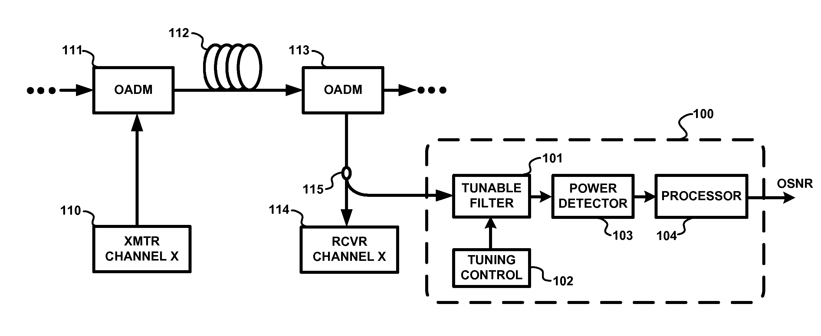
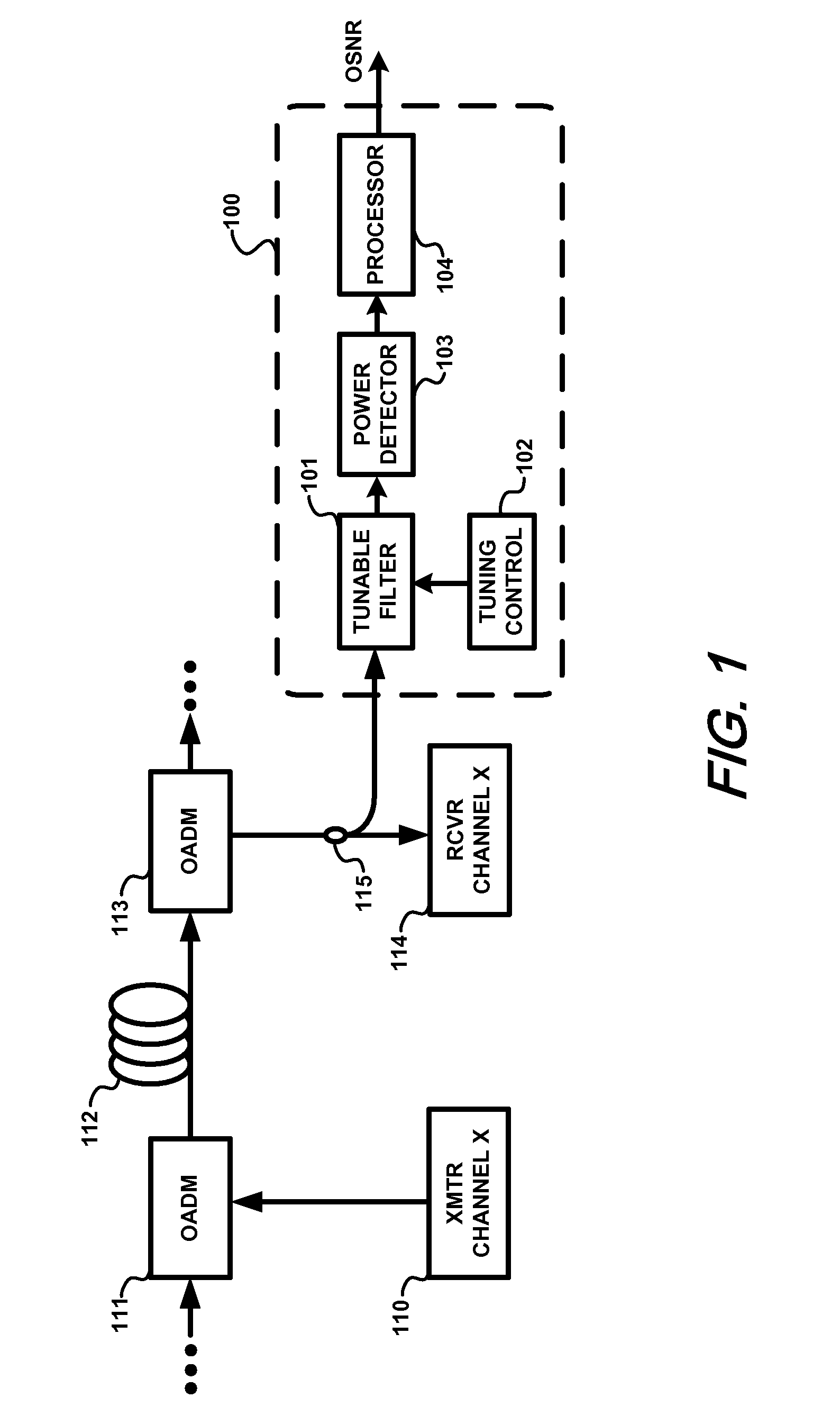
[0007] Because the present invention relies on information obtained after spectrally filtering the signal and noise, its operation is independent of any transmission effect that does not affect the optical power spectra of the signal and the noise or affects them in a known manner. For example, effects such as chromatic dispersion (CD), polarization-mode dispersion (PMD), and changes in the signal degree of polarization (DOP) and noise DOP will not affect the OSNR reading obtained in accordance with the present invention.

Problems solved by technology

If the OSNR is to be monitored within each channel band and the channel bandwidth is not much broader than the signal bandwidth (as in the case of dense WDM), conventional optical spectral measurement techniques for OSNR monitoring become unreliable because it is difficult to distinguish the signal spectrum from the noise spectrum in such a channel.
Unfortunately, this technique becomes unreliable in the presence of polarization-mode dispersion (PMD) and partially polarized noise, although its robustness against PMD can be improved with a special filtering technique, as explained in M. H. Cheung, et al., “PMD-insensitive OSNR monitoring based on polarization-nulling with off-center narrow-band filtering”, IEEE Photonics Technology Letters, Volume 16, Issue 11, 2004, pp.
Disadvantageously, however, the OSNR monitoring method described therein is quite sophisticated and requires several expensive elements such as a phase modulator, a polarization scrambler, and a fiber loop mirror.
Moreover, the measurement time needed to reliably measure the OSNR is long due to the need to align the polarization state of the incoming signal to a certain direction by the polarization scrambler.

Method used


Image

  • Method and apparatus for monitoring optical signal-to-noise ratio
  • Method and apparatus for monitoring optical signal-to-noise ratio
  • Method and apparatus for monitoring optical signal-to-noise ratio

Examples


Embodiment Construction

[0017] The following description is intended to illustrate the principles of the present invention. It will thus be appreciated that those skilled in the art will be able to devise various arrangements that, although not explicitly described or shown herein, embody the principles of the invention and are included within the spirit and scope of the invention. Furthermore, all examples and conditional language recited herein are principally intended expressly to be only for pedagogical purposes to aid the reader in understanding the principles of the invention and the concepts contributed by the inventor(s) to furthering the art, and are to be construed as being without limitation to such specifically recited examples and conditions. Moreover, all statements herein reciting principles, aspects, and embodiments of the invention, as well as specific examples thereof, are intended to encompass both structural and functional equivalents thereof. Additionally, it is intended that such equi...


PUM


Abstract

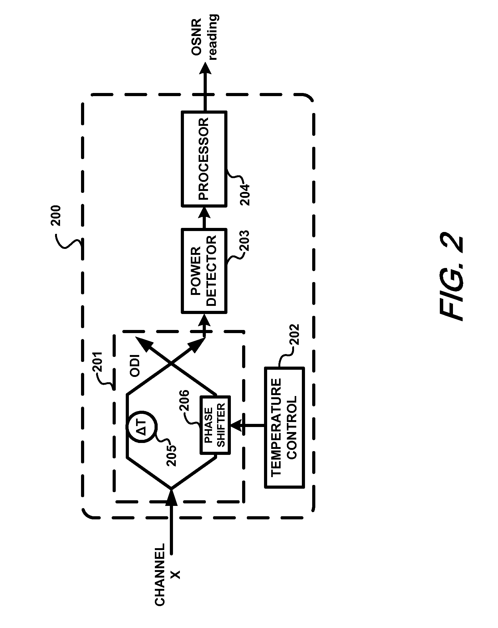
Optical signal-to-noise ratio (OSNR) monitoring methods and apparatus are described. A tunable optical filter filters an optical channel containing an optical signal and noise. The total signal and noise power at the output of the filter is measured as the transmittance passband of the filter is varied and the maximum and minimum powers are determined. The ratio between the maximum and minimum powers is then used to determine the OSNR of the optical channel, which, for example, can be a wavelength channel in a wavelength division multiplexing (WDM) system. The ratio of the maximum signal power to the minimum signal power and the ratio of the maximum noise power to the minimum noise power are pre-determined based on the signal modulation format type and filter passband characteristics. Because the OSNR monitoring method and apparatus rely on information obtained after spectrally filtering the signal and noise, their operation is independent of any transmission effect that does not affect the optical power spectra of the signal and the noise or affects them in a known manner. For example, effects such as chromatic dispersion (CD), polarization-mode dispersion (PMD), and changes in the signal degree of polarization (DOP) and noise DOP will not affect the OSNR reading thus obtained.

Description

FIELD OF THE INVENTION [0001] The present invention relates to the field of high-speed optical communications, and more specifically to monitoring the optical performance of optical communication networks having multiple wavelength channels. BACKGROUND INFORMATION [0002] The capability of monitoring the optical performance of installed optical networks is desired for maintenance and diagnostic purposes. Optical signal-to-noise ratio (OSNR) is a key optical performance indicator, and monitoring the OSNR evolution of an optical transmission link can provide vital information about its performance. In modern optical networks, such as wavelength division multiplexing (WDM) networks, channels may be individually added and dropped at any location. If the OSNR is to be monitored within each channel band and the channel bandwidth is not much broader than the signal bandwidth (as in the case of dense WDM), conventional optical spectral measurement techniques for OSNR monitoring become unreli...

Claims


Application Information

Patent Timeline
Patent Type & Authority Applications(United States)
IPC IPC(8): H01S3/00
CPCH04B10/07953
Inventor KAO, YUAN-HUALIU, XIANG
Owner WSOU INVESTMENTS LLC
Why Eureka
Try Eureka