X-ray shielding device

a shielding device and x-ray technology, applied in the field of x-ray shielding devices, can solve the problems of force to irradiate the human body with x-ray radiation for a relatively longer irradiation time, and is not feasible in terms of design considerations, and achieve the effect of better space-saving configuration

Inactive Publication Date: 2007-12-27
NAT INST OF RADIOLOGICAL SCI 80 +1
View PDF3 Cites 22 Cited by
  • Summary
  • Abstract
  • Description
  • Claims
  • Application Information

AI Technical Summary

Benefits of technology

[0028] As can be appreciated by those skilled in the art, the present invention provides an X-ray shield device having a better space-saving configuration and capable of being arranged in such a manner to automatically move a X-ray shield plate in synchronization with movement of the X-ray source to shield a particular site or area of a subject from the X-ray radiation.

Problems solved by technology

When the X-ray fluoroscopic apparatus is adapted to be used for treatment, however, it can be forced to irradiate the human body with X-ray radiation for relatively longer irradiation time, as compared to diagnosis.
This is not feasible in terms of design considerations because of a limited space between the head of the patient and the X-ray tube of the X-ray fluoroscopic apparatus.
In addition, displacement of an X-ray source of the X-ray fluoroscopic apparatus may require a temporal interruption of the operation and then a manual repositioning of the shielding disk in place.

Method used


Image

  • X-ray shielding device
  • X-ray shielding device
  • X-ray shielding device

Examples


second embodiment

[0158] The second embodiment of the X-ray shield device of the present invention is different from the first embodiment only in the structures of the shielding position determining means and shielding disk size determining means. Only the different structures will be described, and the structures and operations of the second embodiment similar to those of the first embodiment will be omitted.

[0159] Only the components of the second embodiment different from those of the X-ray shield device according to the first embodiment will be described.

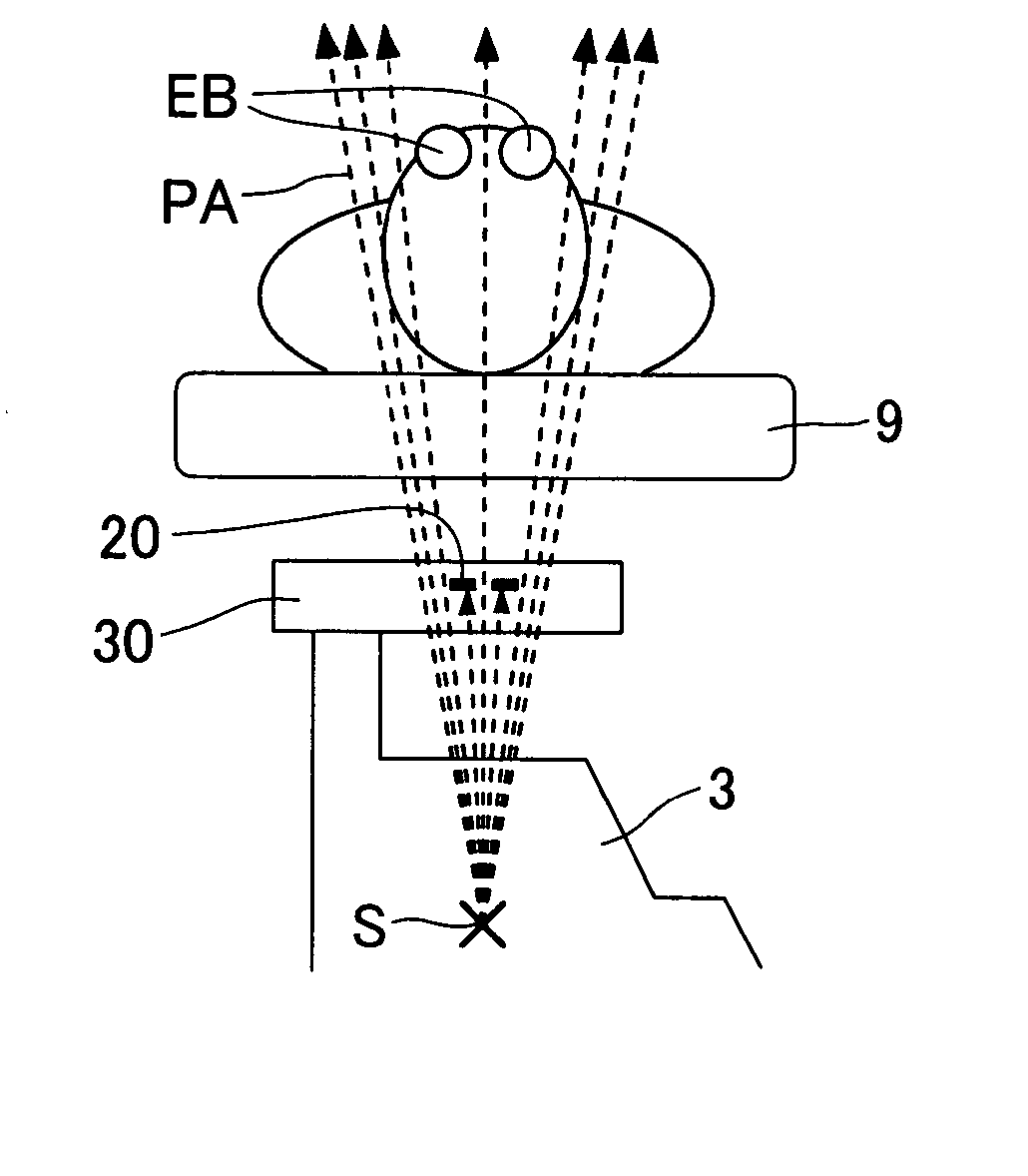
[0160] Shielding position determining means: A shielding position determining means according to the second embodiment determines a shielding position SH on which an X-ray shielding disk 20 should be centered and at which a line extending centrally through the X-ray source S and a position PP of a projection image of an eyeball EB on the projection plane P, intersects the shielding plate movement plane SMP. The shielding position determining me...

examples

[0183] Shielding performance test was performed using an angiographic system available from Toshiba (Trade Name, Circulatory Organ Imager, model / KXO-100G), in which shielding disks 20 each having its diameter of 1.0 cm were respectively mounted on the arm 36 of the shielding disk drive mechanism 30 in the X-ray shield device constructed according to the present invention.

[0184] The shielding disks 20 were of two types, one comprising a layered product consisted of an iron sheet having its thickness of 0.5 mm and a lead sheet having its thickness of 3.0 mm (Example 1) and another comprising a layered product consisted of an iron sheet having its thickness of 0.5 mm and a lead sheet having its thickness of 6.0 mm (Example 2). For comparison with these shielding disks 20, the shielding performance test was also performed without shielding disk.

[0185] The angiographic system was used with a voltage of 80 kV and a current of 125 mA in an X-ray tube used. Three thermo-luminescence dosim...


PUM


Abstract

An X-ray shield device according to one embodiment of the present invention comprises an X-ray shielding plate positioned between an X-ray source and a support member for a subject; a shielding plate driving mechanism including a supporting portion for supporting the X-ray shielding plate, the shielding plate driving mechanism being operable to move the shield plate supported by the supporting portion in a movement plane of the shielding plate perpendicular to a path of X-ray irradiation; and an X-ray shielding plate exchanging means for exchanging the X-ray shielding plate supported by the supporting portion for another X-ray shielding plate of different size.

Description

BACKGROUND OF THE INVENTION [0001] 1. Technical Field [0002] The present invention relates generally to an X-ray shielding device and, more particularly to an X-ray shielding device for preventing a patient from being exposed to a portion of X-ray radiation in an X-ray fluoroscopic apparatus. [0003] 2. Background Art [0004] In medical applications, diagnosis based on an X-ray fluoroscopic apparatus has been traditionally carried out. More recently, the X-ray fluoroscopic apparatus has been also used for treatment procedures in addition diagnosis procedures. [0005] It has been common to treat a patient, for example, suffering from cranial aneurysm by open brain surgery under general anesthesia, but, recently, not a few intravascular surgeries may be conducted. The intravascular surgery may be conducted based on a microcatheter which is delivered through a blood vessel, which may involve use of an X-ray fluoroscopic apparatus (an angiographic system). Such an intravascular surgery may...

Claims


Application Information

Patent Timeline
Patent Type & Authority Applications(United States)
IPC IPC(8): H01J35/16G21K1/02
CPCA61B6/06G21K1/04A61B6/107
Inventor MORITAKE, TAKASHIKOIZUMI, HIROTOONO, HIRONOBU
Owner NAT INST OF RADIOLOGICAL SCI 80
Why Eureka
Try Eureka