Quantification and visualization of the motion and deformation of one or several objects inside a living entity

Inactive Publication Date: 2007-12-27
MATTES JULIAN +4
View PDF2 Cites 50 Cited by
  • Summary
  • Abstract
  • Description
  • Claims
  • Application Information

AI Technical Summary

Benefits of technology

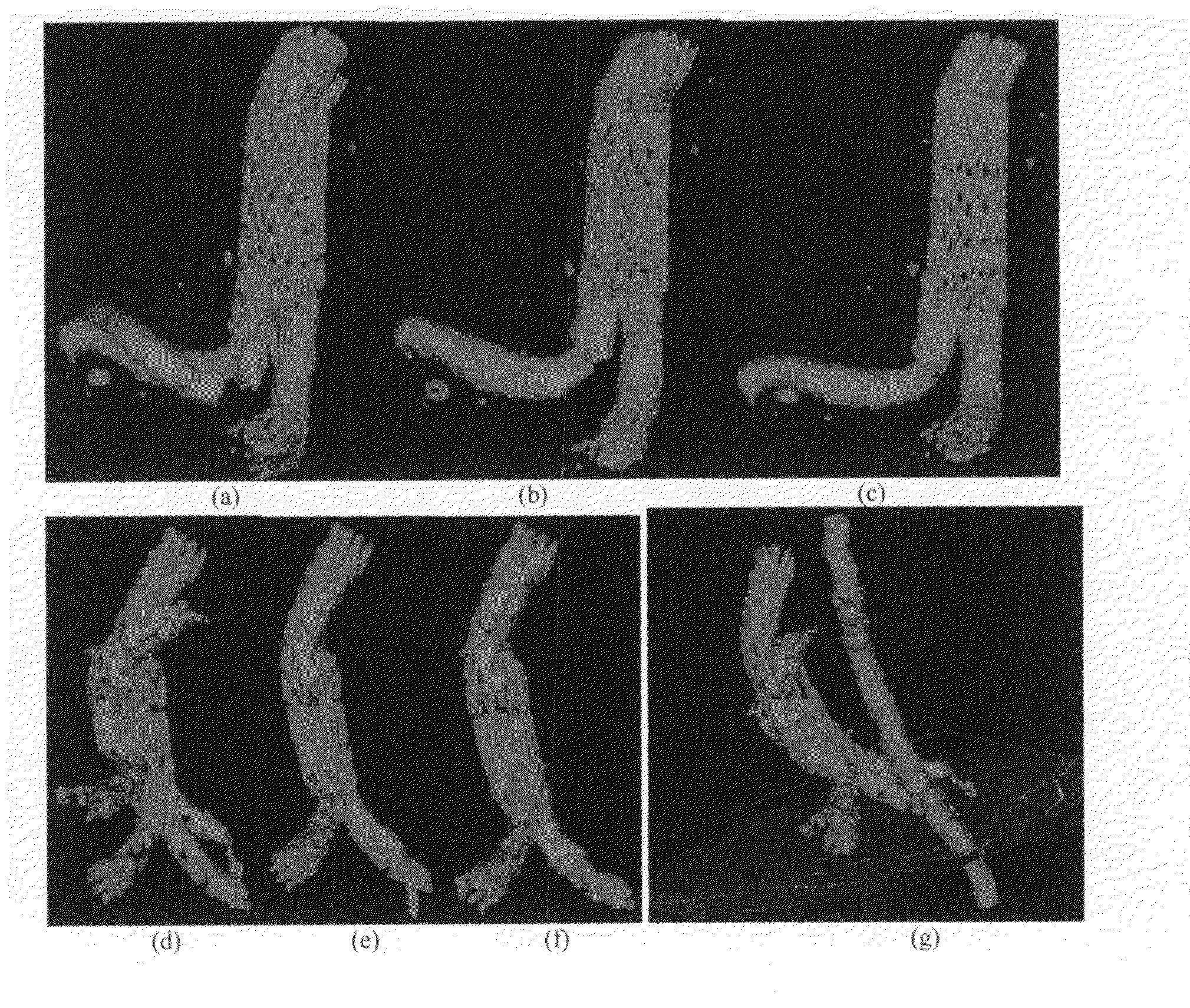
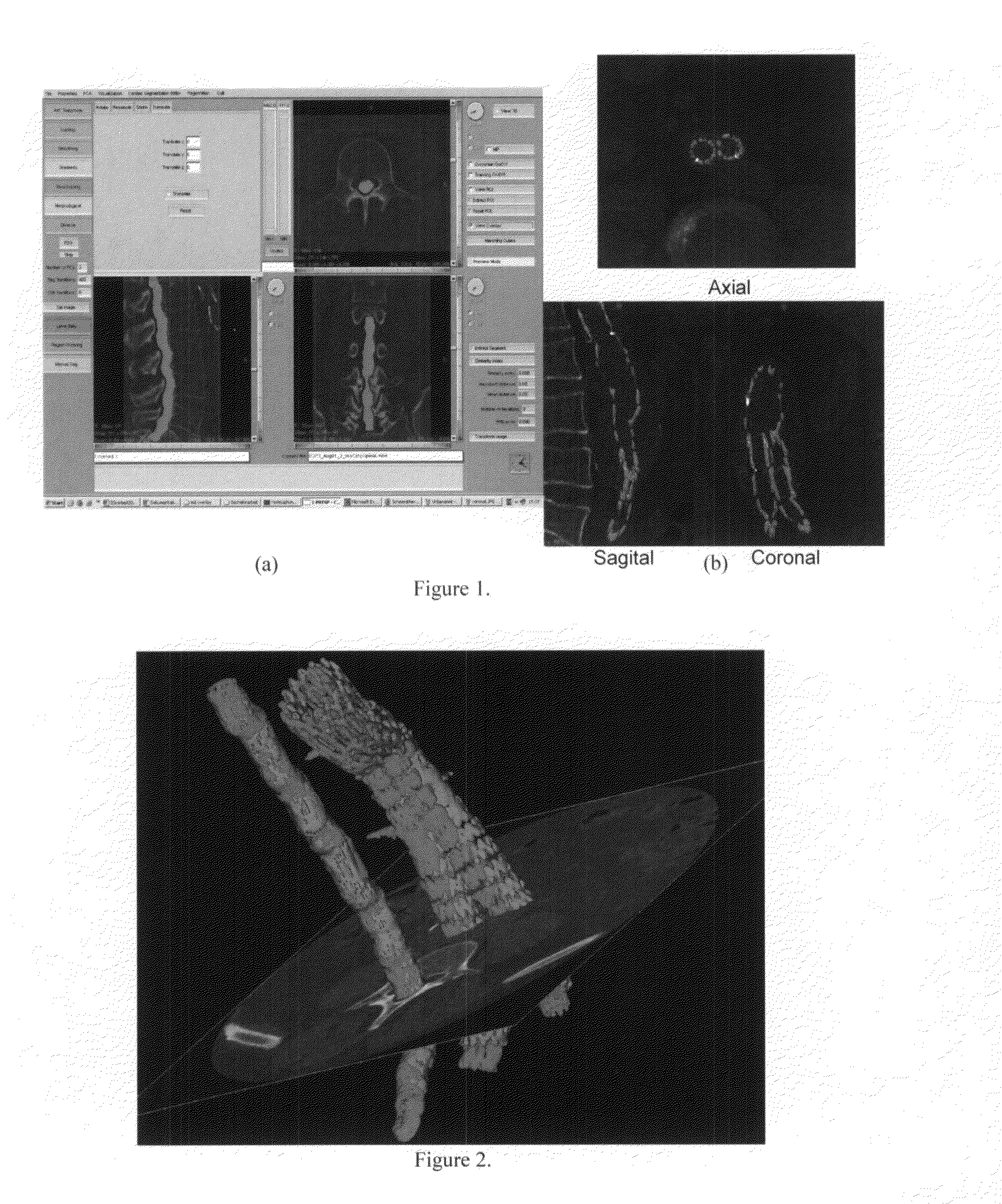
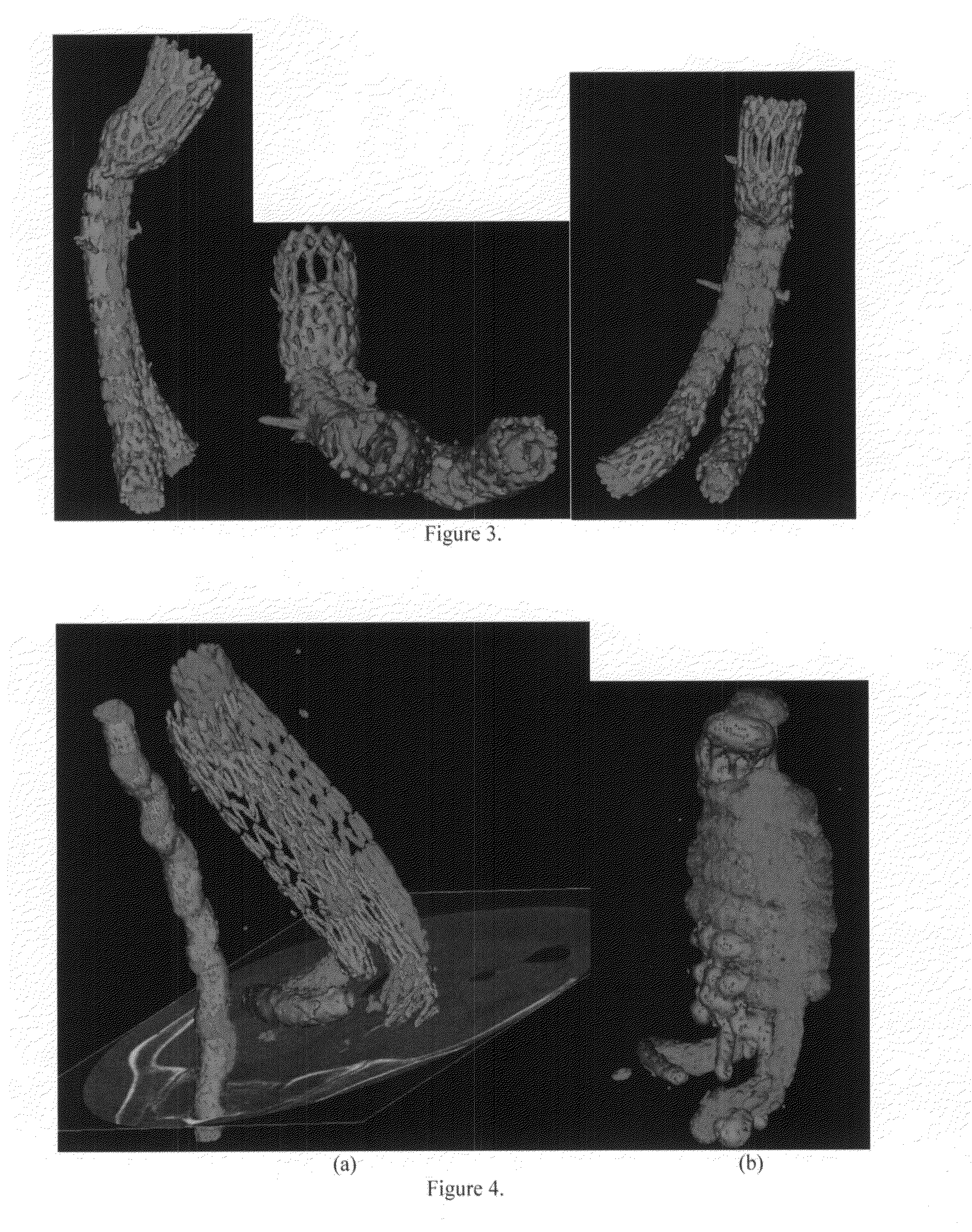
[0014]The invention relates to the quantitative analysis and/or visualization of the relative motion of objects in particular of the relative motion of one or several objects inside a living entity, for instance the human body or a living cell. The invented system and method allow to quantify and visualize the motion of these objects with respect to the parts of the living entity, which can deform and move itself with respect to each other. Furthermore, the method allows to identify movements and deformations which correspond to situations with a particular meaning for the living entity, for instance predicting complications in a disease progress, etc. An important application is the analysis of motion and deformation of s

Problems solved by technology

A patricular challenge is, compared to previous studies of the relative motion of connected vertebras (T. Ishii, Y. Mukai, et al.
A major problem coming up after endovascular stent-graft repair of an abdominal aortic aneurysm (AAA

Method used


Image

  • Quantification and visualization of the motion and deformation of one or several objects inside a living entity
  • Quantification and visualization of the motion and deformation of one or several objects inside a living entity
  • Quantification and visualization of the motion and deformation of one or several objects inside a living entity

Examples


examples

[0054]In a clinical evaluation we investigated a sample of 9 patients all of which have been treated with the same kind of stent-graft device (Zenith). The corresponding CT image stacks consist of slices with 0.9 mm thickness, 0.5 mm x,y-spacing, 512×512 pixels per slice, and a number of 200 up to 250 slices, which we resampled to over 400 slices in order to obtain isotropic images with 0.5 mm thickness. The results are resumed in Table 1.

TABLE 1Migr.ε-SpinalStentPatientCanalMigrationε-Stentε-affinε-12LMsMigr. Aortarel.Aorta10.697.421.260.960.309.404.3420.702.980.210.170.1630.763.220.520.350.143.210.9841.0412.494.021.931.0114.241.8651.107.062.851.680.7161.1119.5121.813.091.2071.115.112.241.210.3481.6311.8710.692.040.8213.603.8291.725.751.711.420.61

[0055]Table 1 shows the quantitative registration results for 9 of the evaluated 22 patients. All distance specifications are indicated in mm. “ε—Spinal Canal” denotes the residual error εr after rigid registration of the spinal canal, “ε—...


PUM


Abstract

The invention relates to the quantitative analysis and/or visualization of the relative motion of objects in particular of the relative motion of one or several objects inside a living entity, for instance the human body or a living cell. The invented system and method allow to quantify and visualize the motion of these objects with respect to the parts of the living entity, which can deform and move itself with respect to each other. Furthermore, the method allows to identify movements and deformations which correspond to situations with a particular meaning for the living entity, for instance predicting complications in a disease progress, etc. An important application is the analysis of motion and deformation of stent-grafts introduced after endovascular repair of aneurysms. Here, the occurrence of deformations leading to graft-limb occlusions and of migrations of the stent-graft leading to so-called endoleaks can be predicted in an early stage. This allows an early intervention, hence, avoiding more severe problems. The motion is calculated from pairs of images corresponding to different points in time using semi-automatic steps to extract point sets (or binary images) and an automatic procedure to determine the motion and deformation of the point sets and to describe it quantitatively. An important part of the method is the visualization allowing the user to have an immediate impression of the occurring movements and deformations.

Description

CROSS REFERENCE TO RELATED APPLICATION[0001]This application claims the benefit of the european patent application No. EP 06 01 3018.4INCORPORATION BY REFERENCE[0002]In its entirety incorporated by reference are the co-pending patent application[0003]Mattes, Eils, Fieres, Demongeot, “Quantitative Analysis, Visualization, . . . ” PCT Patent Application WO 02 / 071333 A2, PCT / EP02 / 02580, filed Mar. 8, 2002 with priority applications 101 11 226.2 DE, filed Mar. 8, 2001 and 101 44 629.2 DE, filed Sep. 11, 2001 (herein afterwards referred to as MEF01) and the articles[0004]Mattes, J., Fieres, J. and Eils, R. A shape adapted motion model for non-rigid registration. In: SPIE Medical Imaging 2002: Image Processing, 2002, 518-527 and[0005]Fritscher, K., R. Schubert. A software framework for preprocessing and level-set segmentation of medical image data. In: SPIE Medical Imaging 2005: Image Processing 1742-1752 and[0006]Handbook of Medical Imaging, Volume 2: Medical Image Processing and Analysi...

Claims


Application Information

Patent Timeline
IPC IPC(8): G06K9/28G06V30/144
CPCG06T7/0081G06T7/2033G06T2207/30101G06T2207/10076G06T19/00G06T7/11G06T7/246
Inventor MATTES, JULIANCHEMELLI-STEINGRUBER, IRISSCHUBERT, RAINERFRITSCHER, KARLNETZER, MICHAEL
Owner MATTES JULIAN
Why Eureka
Try Eureka