Apparatus and method in connection with crane sheave

a technology of apparatus and crane, applied in the direction of dynamo-electric machines, dc source parallel operation, ac network voltage adjustment, etc., can solve the problems of difficult power supply connection with the hook, high cost of custom-made cables, and easy wear and stress of cables, so as to prevent overcharging and facilitate working with cranes , the effect of preventing overcharging

Active Publication Date: 2015-05-07
KONECRANES GLOBAL
View PDF6 Cites 10 Cited by
  • Summary
  • Abstract
  • Description
  • Claims
  • Application Information

AI Technical Summary

Benefits of technology

[0030]Measurements in connection with the hook or the sheave are feasible when it has been possible to generate electric energy there without a separate conductor. Correspondingly, the actuators of the sheave may be in wireless connection to other devices of the crane, whereby measurement and state data can be combined among various parts of the crane. A wireless connection for example between the hoist motor and the hook of the crane may thus serve bidirectionally and in two different meanings. Then, the load sensors may control the collector circuit and prevent energy from being collected if the load requirements are not met, i.e. if the torque driving the sheave is not sufficiently high. The torque can be measured, and the measurement result can be used as one alternative for activating the...

Problems solved by technology

In a crane having a trolley which moves supported by a horizontal girder, i.e. a bridge, and from which a sheave carrying the hook is suspended via a rope or chain, supplying power in connection with the hook is difficult because the hook moves vertically relative to the crane trolley and horizontally when the trolley and the bridge are moving in lateral directions.
If power supply is required for the hook or some other type of catch, the cable used is custom-made and thus expensive.
The cable is also sensitive to wearing and stress.
Also with regard to its structure, such a solution is expensive and difficult to implement, although such solutions are used when required, particularly in large cranes.
There would be many applications for power supply in connection with a hook, also in smaller cranes in which providing power supply in connection with the hook would be unreasonably expensive proportioned to the price of the crane.
However, applying known structures to cranes involves some particular problems.
There are certain problems in the techniques disclosed in the above references.
For example when the crane hook is supported against the crane frame via a flexible stru...

Method used


Image

  • Apparatus and method in connection with crane sheave
  • Apparatus and method in connection with crane sheave
  • Apparatus and method in connection with crane sheave

Examples


Embodiment Construction

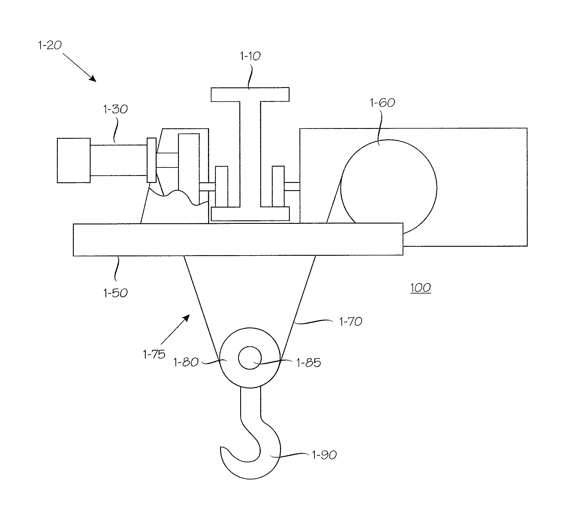
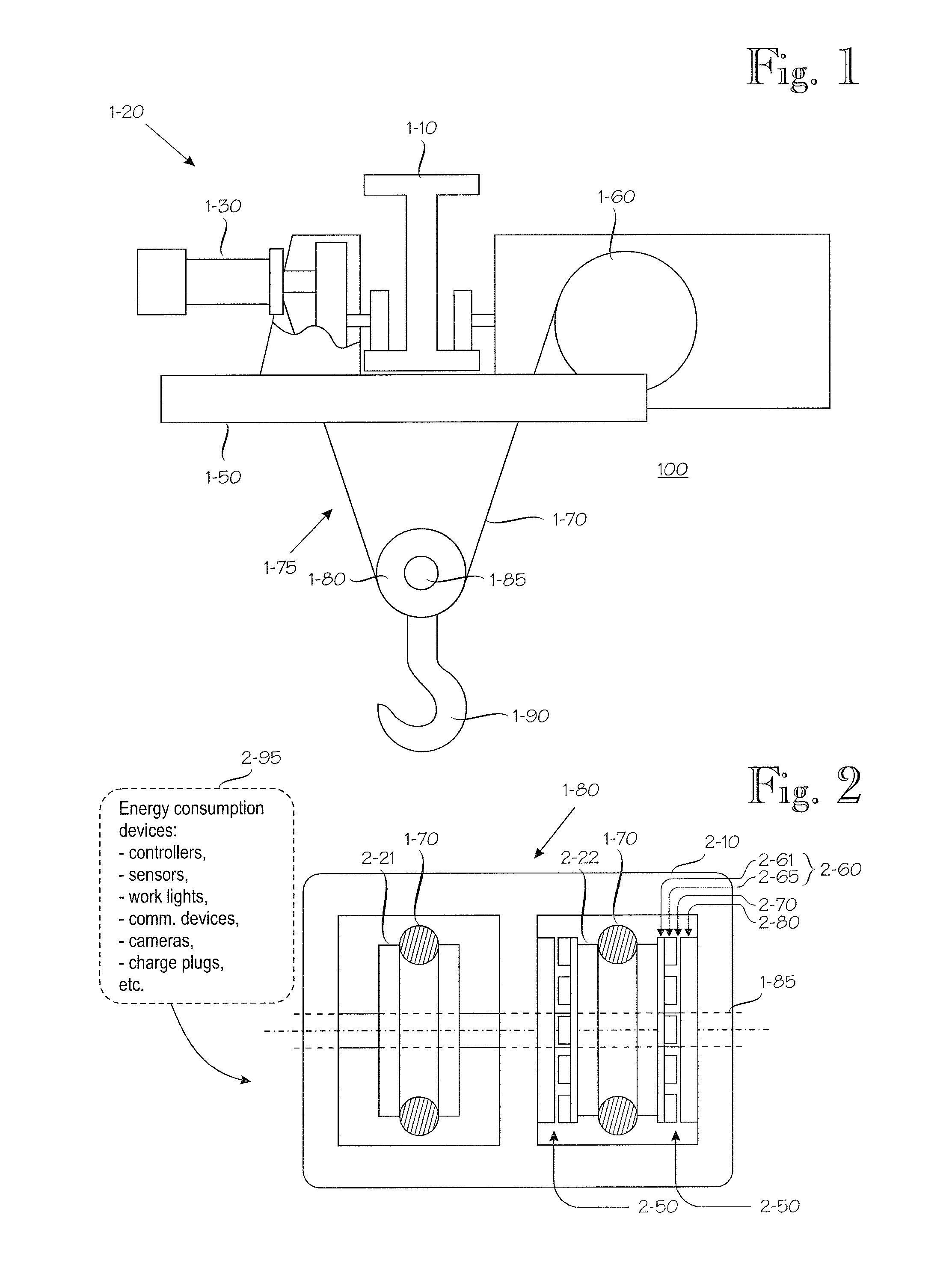
[0062]FIG. 1 shows the main parts of an exemplary crane. The hoisting machine is generally denoted by reference numeral 100. In this example, the crane frame comprises a girder 1-10, in the longitudinal direction of which travels a trolley 1-20 driven by a motor 1-30. The body 1-50 of the trolley supports a hoist motor 1-60, which lifts and lowers, via tackle 1-70, elements indicated generally by reference numeral 1-75 and comprising a sheave arrangement 1-80 and a load-fixing means 1-90 rising and lowering with it, such as a hook, clamshell or catch. Many conventional elements of the hoisting machine, such as different rope drums, are not described in more detail. From the point of view of the invention, the most interesting element is the sheave arrangement 1-80 described in more detail in FIG. 2. Reference numeral 1-85 denotes the shaft of the sheave system.

[0063]FIG. 2 shows positioning the parts of an energy collector in a load-fixing means provided with a sheave in accordance ...


PUM


Abstract

An apparatus for collecting energy in connection with a sheave system in a hoisting apparatus provided with a sheave system. The apparatus includes at least one generator including a rotor and at least one stator. The rotor is connected rigidly to a sheave of the sheave system, and the at least one stator is connected rigidly to the sheave system such that when the load of the hoisting apparatus is rising or lowering, said at least one sheave rotates, whereby the rotor rotates simultaneously but the stator does not rotate, whereby electric energy is induced in the stator. The apparatus further includes electric energy storage, a device for modifying induced electric energy and storing it in energy storage; and a device for supplying energy from the energy storage to at least one consumption device. The consumption device may be, for example, a working lamp, sensor, measuring device, communications device, signal device, charging plug or a combination of these mounted in connection with the sheave system.

Description

FIELD OF THE INVENTION[0001]The invention relates to techniques with which apparatuses requiring electricity can be mounted on hoisting machines, such as cranes or the like, in connection with a sheave, particularly a sheave moving along with a hook or another load-fixing means. The invention relates to a crane or a hoist in which a hook or the like is lifted and lowered by a rope or chain passing through at least one sheave, whereby the sheave turns the linear movement of the rope into rotating movement. The use of the invention is not, however, restricted to sheaves moving along with a hook or the like but the invention may be used with other sheaves as well.BACKGROUND OF THE INVENTION[0002]In the following description, the terms ‘crane’ and ‘hoisting machine’ or ‘hoisting apparatus’ are used as synonyms. Correspondingly, the term ‘hook’ is used to refer to all types of load-fixing means. In this description, ‘down’ means, as usual, the direction in which gravitation tends to draw...

Claims


Application Information

Patent Timeline
IPC IPC(8): B66C13/00B66D1/28H02J7/00H02J1/10H02J7/35F03G1/00B66C13/16H02K7/18
CPCB66C13/00B66C13/16B66D1/28H02J7/0068H02J1/10H02J7/35F03G1/00H02K7/1853B66C13/28
Inventor MESIA, HEIKKIERIKSSON, LASSELINDFORS, HANNUSCHLESIER, KIMVUORELA, TIMOINKINEN, MIKAMYRY, MANURUUSKANEN, PEKKAJAASKELAINEN, MIKKOPAJU, MARTTI
Owner KONECRANES GLOBAL
Why Eureka
Try Eureka