
Ball joint device, manufacturing process and apparatus

Inactive Publication Date: 2007-12-27
IND AUXILIAR ALAVESA S A INAUXA
View PDF25 Cites 3 Cited by
  • Summary
  • Abstract
  • Description
  • Claims
  • Application Information

AI Technical Summary

Benefits of technology

[0008] The design of the joining means and the areas in contact of the components of the ball joint device in the joining surfaces assures the tightness required in this type of devices.
[0009] The relation between the casing and the seating also allows the casing to be designed such that it can be adapted to different applications according to the system in which the ball joint device is going to be incorporated.
[0011] Given that the over-injected material cools and ends up solidifying on the ball joint by means of the manufacturing process of the invention, there is always an adjustment between the bowl and the ball joint, therefore the dimensional tolerances as regards the diameter of the ball joint are not as demanding. This also allows lowering the manufacturing costs of the ball joint.
[0022] Likewise, the dust seal can further comprise a plurality of ring-shaped grooves acting as a labyrinthine seal on a contact surface between the first end and the ball joint so as to assure tightness between the dust seal and the ball joint.

Problems solved by technology

This high degree of precision in the manufacture is necessary because it could even happen that the assembly is not possible if the tolerances of the components are too wide or if, even in the event that they are more restrictive, the manufactured pieces do not comply with said design tolerances; these tolerances will also have a repercussion in the performance of the device.
The ball joint devices with unsuitable tolerances cause a series of inadmissible defects.
These defects, in addition to being observable in a recently manufactured device, entail a premature deterioration of the device, shorten its working life and affect the use of the device.
The devices known in the state of the art have a design and construction which do not facilitate this ability to be integrated in a system in a manner that can be easily adapted to different systems because they require the system itself to be modified for this.

Method used


Image

  • Ball joint device, manufacturing process and apparatus
  • Ball joint device, manufacturing process and apparatus
  • Ball joint device, manufacturing process and apparatus

Examples


Embodiment Construction

)

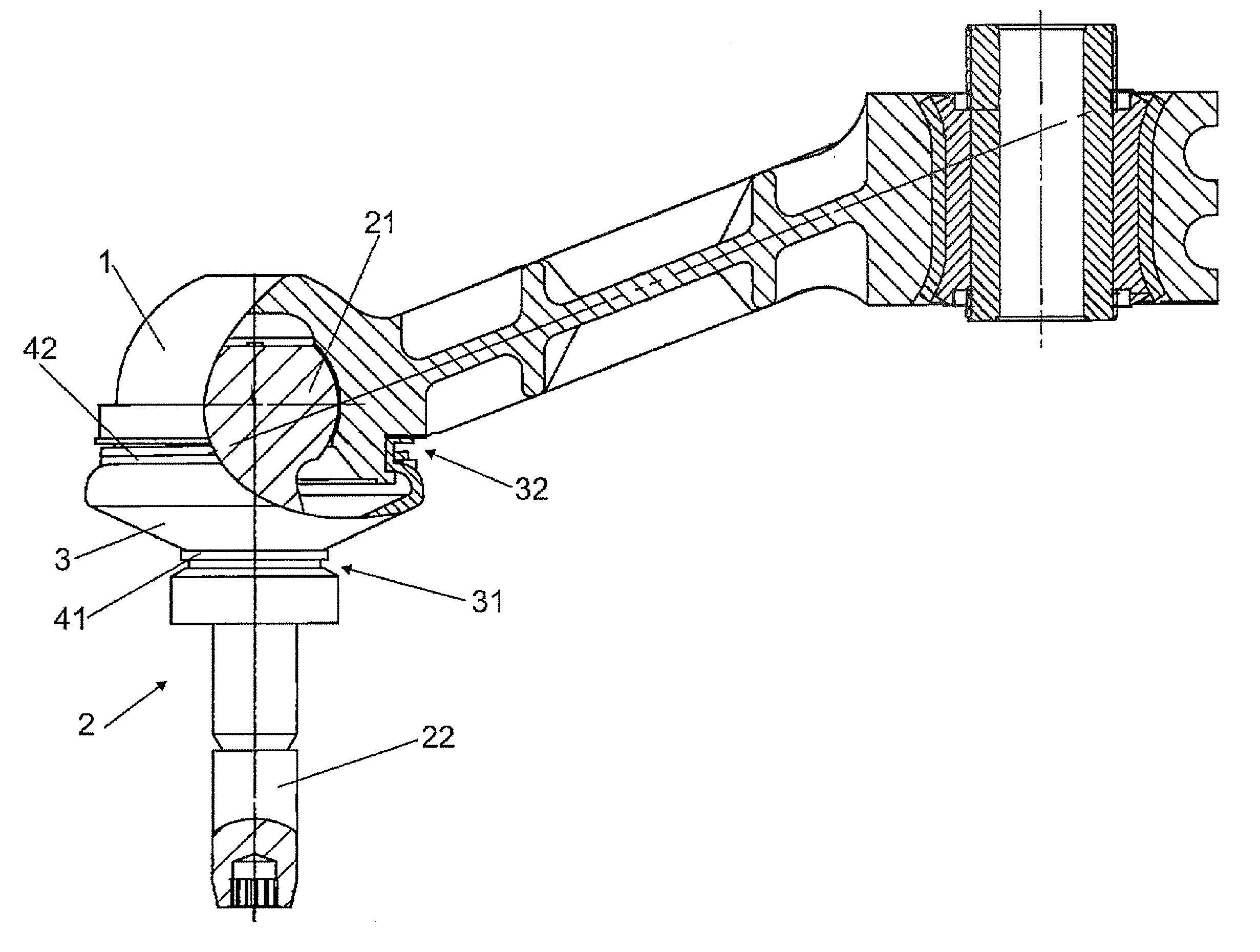
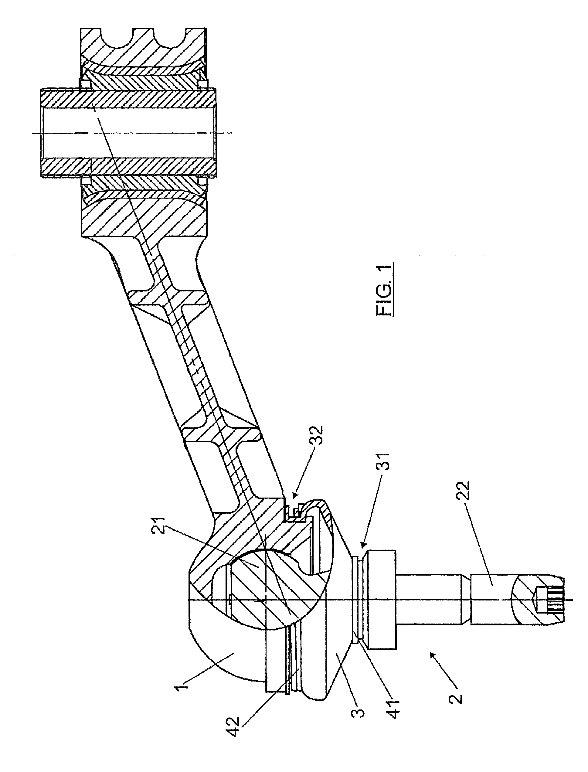
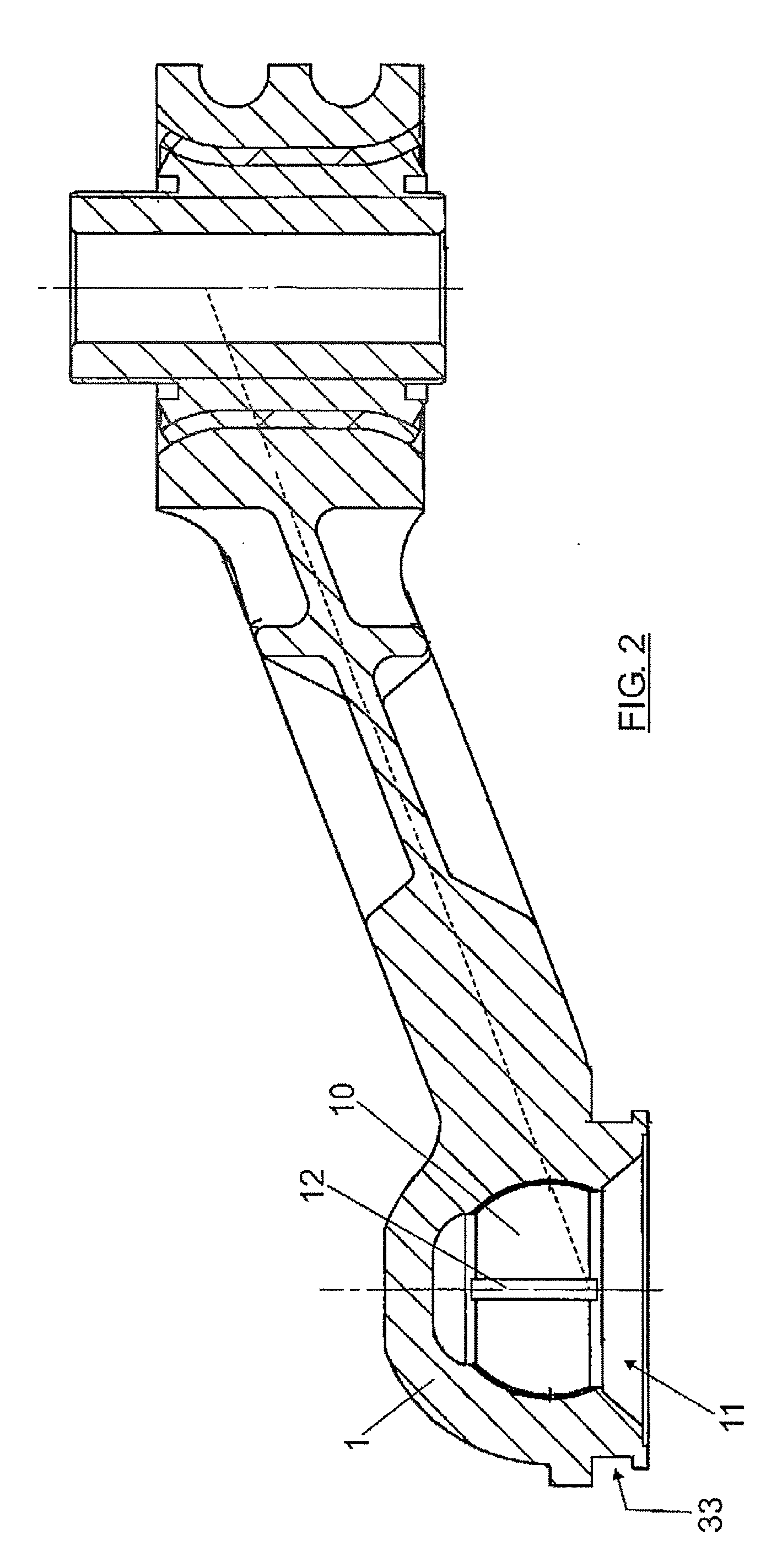
[0082] A preferred embodiment of the invention is described below with the help of drawings. Thus, according to the embodiment, the ball joint device can comprise: [0083] a ball joint 2 comprising a first substantially spherical ball joint portion 21 and a second ball joint portion 22 having a rod shape; [0084] a casing 1; wherein: [0085] the casing 1 comprises: [0086] a housing 10 for housing the first ball joint portion 21, said housing 10 being configured so as to allow sliding movement of the first ball joint portion 21 in said housing 10; [0087] an opening 11 configured so as to allow the first ball joint portion 21 to be introduced in said housing 10.

[0088] The casing 1 can further comprise a plurality of channels 12 in an inner surface of the housing 10, said channels 12 being configured so as to allow distribution of a lubricant between the first ball joint portion 21 and the inner surface of the housing 10.

[0089] An embodiment of the invention can further comprise a dust...


PUM

PropertyMeasurementUnit
Temperatureaaaaaaaaaa
Timeaaaaaaaaaa

Abstract

The invention relates to a device, a process and an apparatus for manufacturing a ball joint device having a ball joint and a casing (1). The casing (1) has a housing (10) for housing the ball joint (2), said housing (10) being configured so as to allow a sliding movement of the first ball joint portion (21) in the housing (10). The apparatus has: containment devices (100) for defining a cavity (110) between the surface to be over-injected and the containment devices (100); entrance devices (200) in the containment devices (100), so that the over-injection product can be introduced in the cavity (110).

Description

FIELD OF THE INVENTION [0001] The invention relates to a ball joint device of the type used in automotion, to the manufacturing process of said ball joint device as well as the apparatus wherein the device is manufactured according to the process. BACKGROUND OF THE INVENTION [0002] Various embodiments describing the ball joint devices are known in the state of the art. [0003] Nevertheless, the embodiments proposed in the state of the art require a precise adjustment both in the manufacture and in the later assembly of the components of the device. This high degree of precision in the manufacture is necessary because it could even happen that the assembly is not possible if the tolerances of the components are too wide or if, even in the event that they are more restrictive, the manufactured pieces do not comply with said design tolerances; these tolerances will also have a repercussion in the performance of the device. [0004] The ball joint devices with unsuitable tolerances cause a...

Claims


Application Information

Patent Timeline
IPC IPC(8): F16C11/06
CPCB29C45/0053Y10T403/32729B29C45/16B29C45/34B29C2045/0079B60G7/001B60G2204/41B60G2204/416B60G2206/11B60G2206/8101F16C7/02F16C11/0619F16C11/0623F16C27/02B29C45/14426F16C2326/05
Inventor MORALES ARNAEZ, AGUSTIN
Owner IND AUXILIAR ALAVESA S A INAUXA
Learn More