Programmable energy saving register vent

Inactive Publication Date: 2007-12-27
SPRINGFIELD ACQUISITION CO LLC
View PDF19 Cites 37 Cited by
  • Summary
  • Abstract
  • Description
  • Claims
  • Application Information

AI Technical Summary

Benefits of technology

[0026]An advantage of the present invention is that it provides an energy saving floor, ceiling and/or wall register vent that allows users to shut off the flow of heat or air conditioning in select rooms via an internal controller.
[0027]Another advantage of the present invention is that it provides a multi-zone heating and cooling system that allows users to shut down rooms at programmed times to reduce the amount of energy wasted on heating or cooling inactive areas of the home
[0028]Yet another advantage of the present invention is that it provides

Problems solved by technology

Although these are effective ways of reducing heating and cooling costs, there can be a high capital cost associated with such installations, and a significant inconvenience to the building occupants during installation.
This method has the disadvantage of reducing the comfort of the building environment.
This is a tedious and time consuming process.
Additionally, when a person may be in a hurry to leave the building or home, as when leaving for work, it is easy to overlook the need to adjust the vents, which problem is exacerbated if there are numerous vents to open or close.
Firstly, the system requires relatively expensive modified ductwork including the motorized dampers and wiring thereto, which is even more costly to retrofit into an existing system as the ducts may be hidden in walls, floors or ceilings, thereby requiring modification of the structure with the attendant inconvenience, mess and expense.
Additionally, the furnace controller, or other controller, needs to be compatible with the motorized dampers, and existing systems generally do not have this capability, which then requires a new furnace when an HVAC system is retrofitted, which again is a very costly expense.
Further, the installation or retrofitting of such systems typically requires professional installation technicians, with their attendant cost and scheduling issues, and is therefore not easily accomplished by a typical

Method used


Image

  • Programmable energy saving register vent
  • Programmable energy saving register vent
  • Programmable energy saving register vent

Examples


Example

[0062]Corresponding reference characters indicate corresponding parts throughout the several views. The exemplifications set out herein illustrate one preferred embodiment of the invention, in one form, and such exemplifications are not to be construed as limiting the scope of the invention in any manner.

DETAILED DESCRIPTION OF THE INVENTION

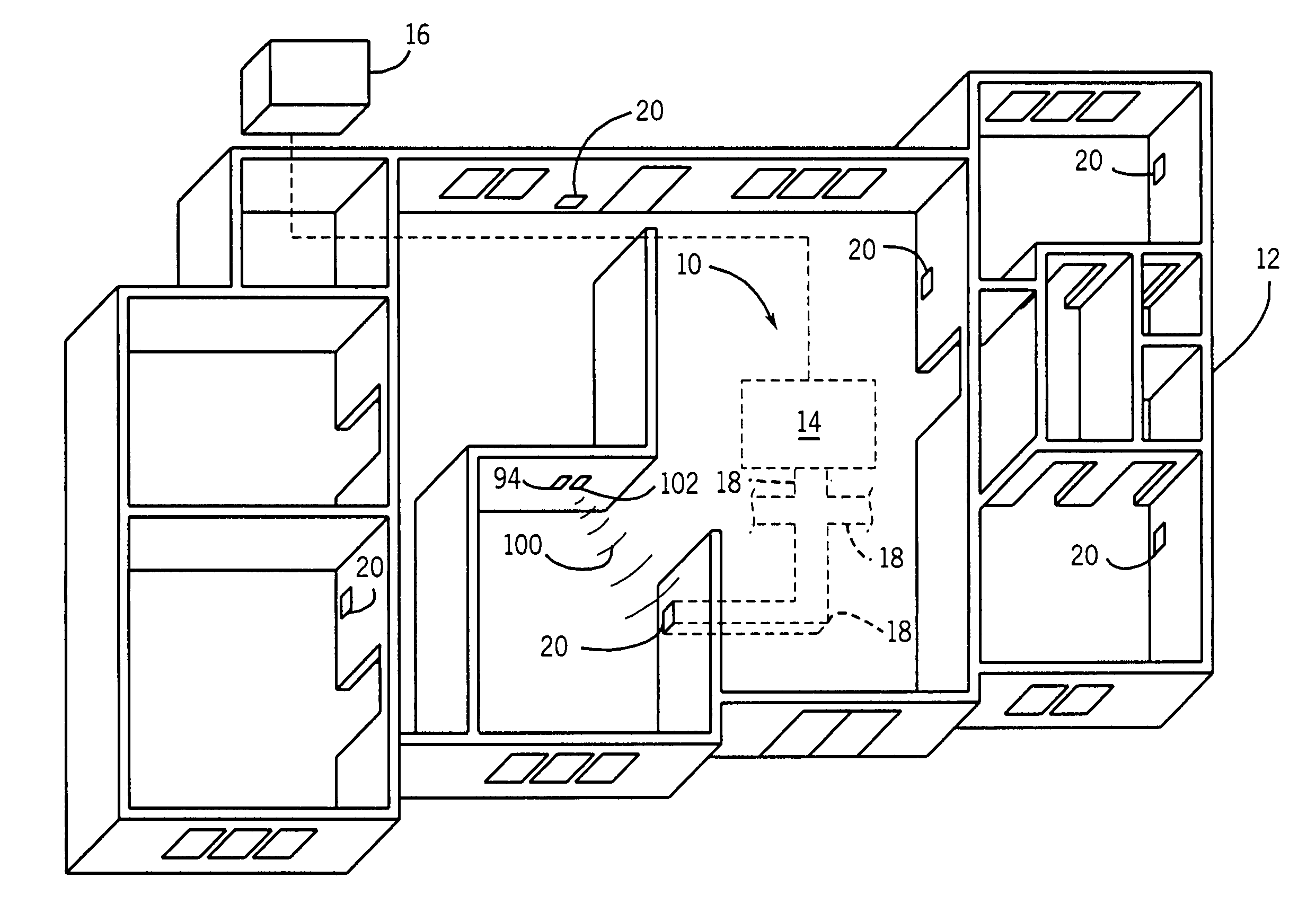
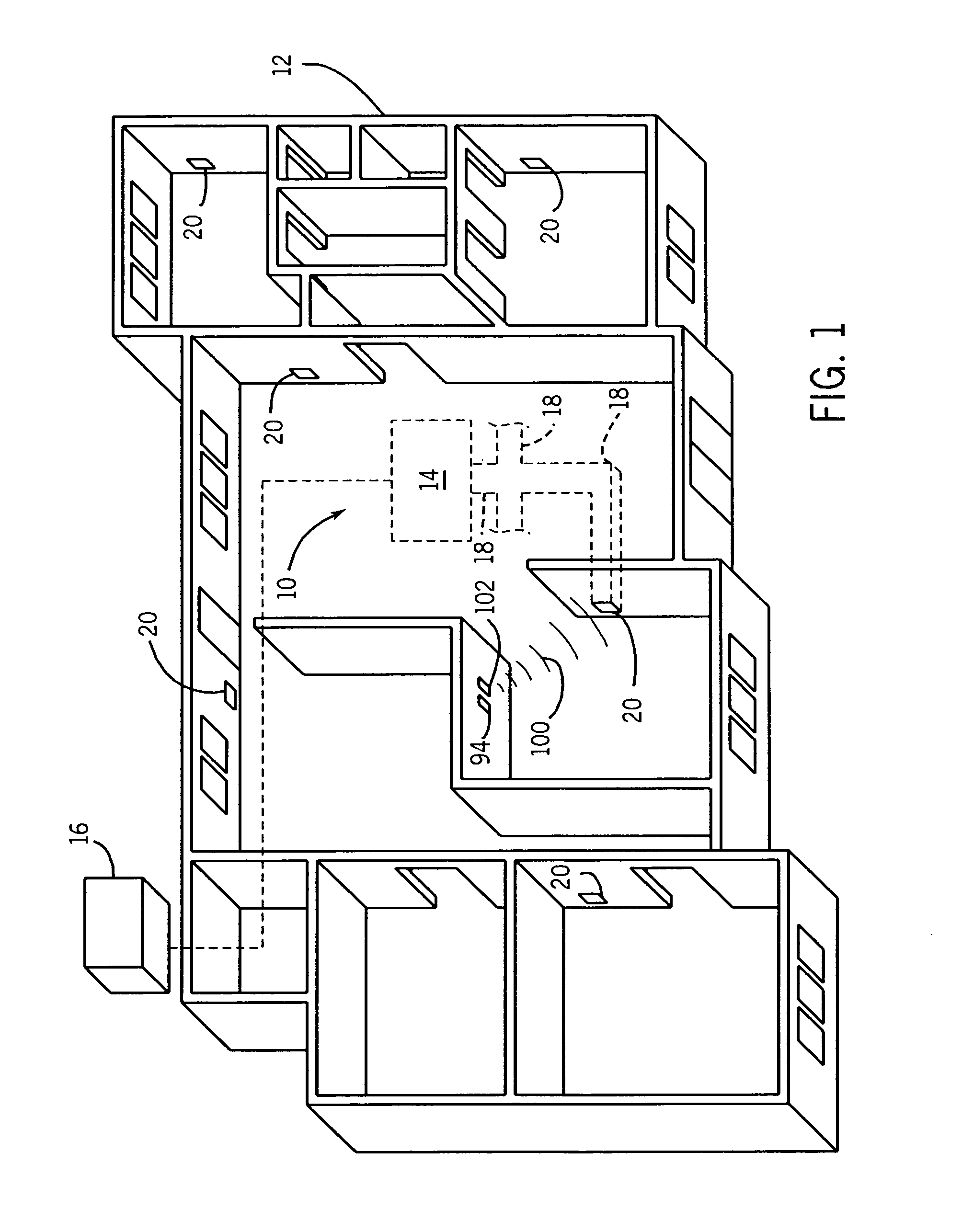
[0063]With initial reference to FIG. 1, there is shown a building environmental air temperature control system 10, such as an HVAC system, located in building 12. System 10 can include at least one of a heating system and a cooling system, such as furnace 14 connected to air conditioning compressor 16. Furnace 14 can typically be a forced air system including a burner / heat exchanger unit and a blower (all not shown), or alternatively a gravity system, or other system. Further, furnace 14 can include other elements such as controls and thermostats (also not shown). At least one duct 18 is connected to furnace 14. Programmable vents 20 are connecte...


PUM


Abstract

A programmable vent for a duct used with a building environmental air temperature control system. The programmable vent includes a vent housing with a front face which has an inset, where the vent housing is configured to allow air flow from the duct. At least one louver is movably connected to the vent housing, an actuator is connected to the at least one louver, a controller module is removably attached to the vent housing and positioned in the inset, the controller module being connected to the actuator when positioned in the inset.

Description

CROSS-REFERENCE TO RELATED APPLICATION[0001]This is a non-provisional application which claims the priority benefit of U.S. provisional patent application Ser. No. 60 / 815,702, entitled “PROGRAMMABLE ENERGY SAVING REGISTER VENT”, filed Jun. 22, 2006; and U.S. provisional patent application Ser. No. 60 / 837,155, entitled “PROGRAMMABLE ENERGY SAVING REGISTER VENT”, filed Aug. 11, 2006.BACKGROUND OF THE INVENTION[0002]1. Field of the Invention[0003]The present invention relates to building environmental air temperature control systems, and, more particularly, to programmable duct vents for such systems.[0004]2. Description of the Related Art[0005]Known heating, ventilation and air conditioning (HVAC) systems can include a thermostatically controlled furnace unit connected to ducts, where the ducts terminate in louvered vents. An air conditioning compressor with an evaporator coil is connected to the furnace unit. For heating, a blower circulates air across a heat exchanger / burner within ...

Claims


Application Information

Patent Timeline
IPC IPC(8): F24F11/00
CPCF24F11/0012F24F2011/0068F24F13/15F24F11/04F24F11/30F24F2110/10F24F11/56F24F11/74F24F11/52
Inventor HUDON, STEVENBREWER, DAVIDSAFRONCHIK, VALERYCHENG, MANG
Owner SPRINGFIELD ACQUISITION CO LLC
Why Eureka
Try Eureka