Method for Optimizing of Pipeline Structure Placement

a pipeline structure and optimization method technology, applied in the field of performance optimization of integrated circuits, can solve the problems of missing performance objectives, timing violations, and specific logic connectivity scenarios that have not responded well to this methodology approach, and achieve the effect of improving pipeline placement and timing quality, preserving quality, and saving manpower and elapsed tim

Inactive Publication Date: 2007-12-27
GLOBALFOUNDRIES INC
View PDF1 Cites 8 Cited by
  • Summary
  • Abstract
  • Description
  • Claims
  • Application Information

AI Technical Summary

Benefits of technology

[0011]As a result of the summarized invention, technically we have achieved a solution which corrects pipeline structure timing violations for an entire class of pipeline profiles—both simple latch to latch, and mixed logic pipeline configurations. The solution preserves the quality of the overall design's placement and timing while improving the quality of pipeline placement and timing in an automated process. This approach realizes a significant savings in both the manpower and elapsed time required to solve the problem.

Problems solved by technology

However, certain specific logic connectivity scenarios and physical configurations have not responded well to this methodology approach.
The placement of logic pipelines in response to standard design optimization tools and algorithms has been poor—resulting in timing violations and missed performance objectives.
Creation of the scripts carried with it an overhead in manpower and design time.
More problematic was the fact that this approach was not very effective for complex pipeline structures.
In such cases the ineffectiveness of simple scripts forced designers to resort to more manually directed operations.
These operations carried a considerable burden in manpower, and had a considerable impact on design closure schedules.

Method used


Image

  • Method for Optimizing of Pipeline Structure Placement
  • Method for Optimizing of Pipeline Structure Placement
  • Method for Optimizing of Pipeline Structure Placement

Examples


Embodiment Construction

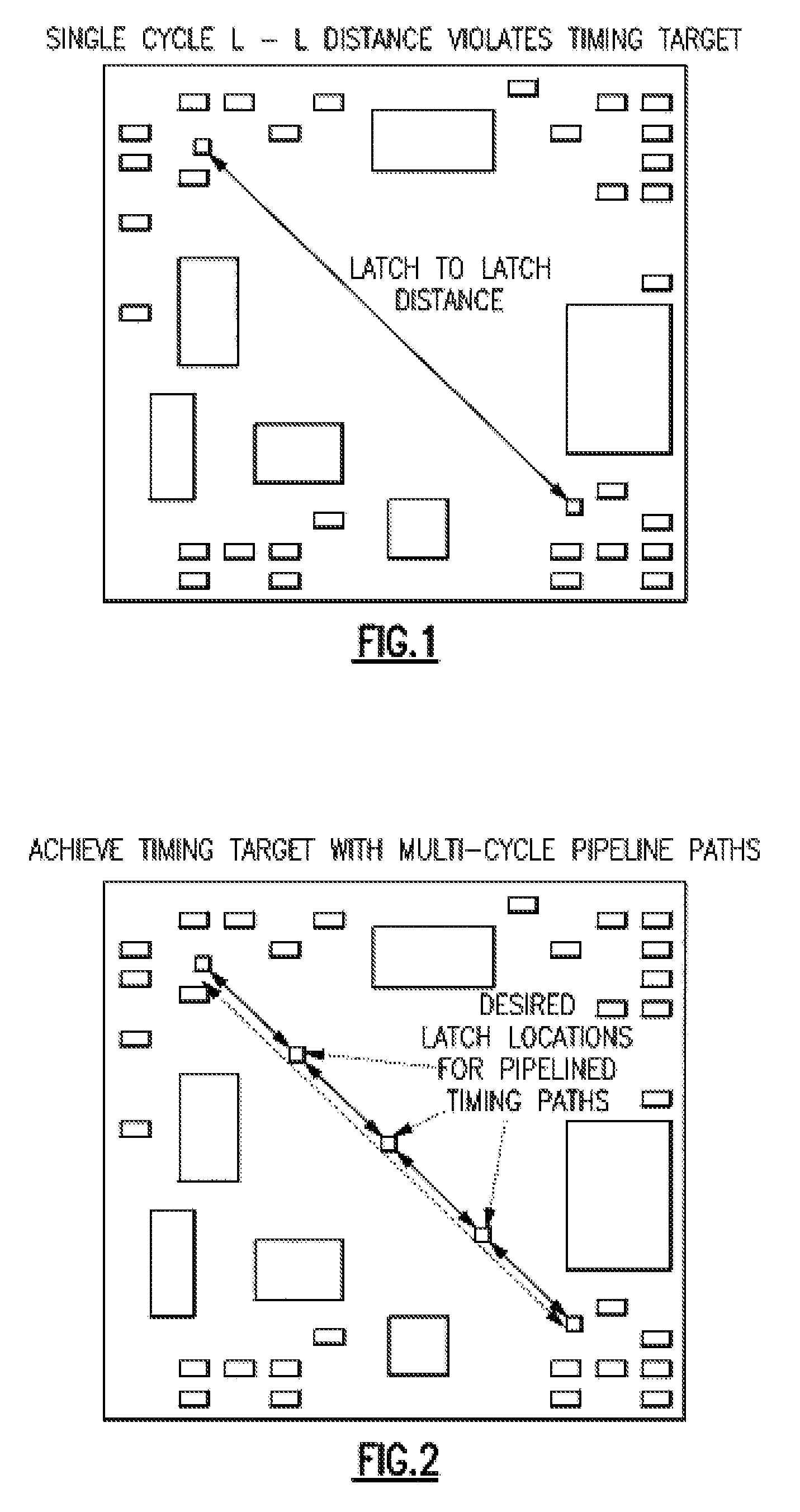
[0031]As chip cycle times have decreased, chip sizes and integration levels have increased. These factors have conspired to produce an ever increasing population of excessive path source-to-sink distances (FIG. 1). The ability to close timing on these paths ranges from problematic to impossible. Often these long path distances are non-negotiable due to Floor planning and logic global connectivity constraints. When possible, designers seek to traverse the distance in multiple cycles by means of a sequence (pipeline) of timing paths which meet their individual single cycle time requirements. As a result, pipeline usage is becoming more prevalent

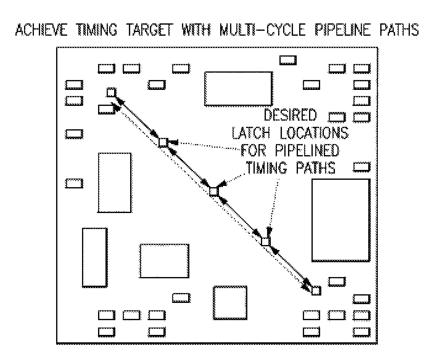
[0032]The designer's desire and expectation is that the individual single cycle paths will be placed in such a way that the multi-cycle distance will be partitioned into equal subdivisions—each subdivision path distance being short enough to support its single cycle timing requirement (FIG. 2).

[0033]Increased usage of pipeline structures has gi...


PUM


Abstract

Using a computer and storage, a circuit design process is executed to preserve overall design quality while obtaining quality placements for a full class of pipeline structure signatures. These signatures include classic latch to latch pipelines, as well as a variety of latch to latch and mixed logic pipelines. The process employs a method for optimizing pipeline structure placement in a circuit design, by initiating an analysis of pipeline logic structures for correcting poor quality of result (QOR) placements by identifying poor placements caused by placement algorithmic response to degenerate cases and in the process of analysis preserving high quality placements of global placement and timing to preserve preponderant non-degenerate cases in said circuit design. Then employing a plurality of global placement steps, wherein each subsequent placement's quality of result (QOR) is dependent upon the prior placement's quality of result (QOR), circuits are identified as being involved in a class of degenerate cases, and circuits having poor placements are removed by unplacing them from the global placement solution and also other non-degenerate poor quality placements are corrected.

Description

TRADEMARKS[0001]IBM® is a registered trademark of International Business Machines Corporation, Armonk, N.Y., U.S.A. Other names used herein may be registered trademarks, trademarks or product names of International Business Machines Corporation or other companies.BACKGROUND OF THE INVENTION[0002]1. Field of the Invention[0003]This invention relates to the performance optimization of integrated circuit (IC) designs, and particularly to a faster, more efficient approach to timing closure for integrated circuit designs containing pipeline logic structures, especially where the logic compositions of said pipelines structures are unrestricted in their definition[0004]2. Description of Background[0005]Within IBM automated design of integrated circuits generally employs a suite (mix) of IBM design tools and algorithms to simultaneously address the problems of performance optimization and full design wireability, such as those netweight solutions described in US Patent of Publication Number...

Claims


Application Information

Patent Timeline
Patent Type & Authority Applications(United States)
IPC IPC(8): G06F17/50
CPCG06F17/5081G06F17/5072G06F30/392G06F30/398
Inventor CURTIN, JAMES J.SEARCH, DOUGLAS S.
Owner GLOBALFOUNDRIES INC
Why Eureka
Try Eureka