Composite floor and composite steel stud wall construction systems

a technology of composite steel studs and floor, applied in the direction of structural elements, building components, building reinforcements, etc., can solve the problems of significant reduction of the load-carrying capacity of eccentric bearing walls, significant delay in waiting for concrete to cure, and high cost of eccentric bearing details, etc., to achieve enhanced structural strength and stiffness, and reduce steel stud costs

Inactive Publication Date: 2008-01-03
SIU WILFRED W
View PDF52 Cites 27 Cited by
  • Summary
  • Abstract
  • Description
  • Claims
  • Application Information

AI Technical Summary

Benefits of technology

[0068] Reduced steel stud costs (and/or enhanced structural strengt...

Problems solved by technology

The fact that subsequent floor construction follows the completion of the floor assembly below means a significant delay in waiting for the concrete to cure.
This very premise, however, creates eccentricity in the loading, and significantly reduces the load-carrying capacity of the bearing wall.
With significantly increased spans associated with these more common systems, the eccentric bearing details become costly and complicated.
The limitations of this composite beam include the minimal thickness of cover concrete available for composite action, the expense of the extension, and the amount of welding required for composite action.
In either case, perimeter stud walls are not designed for errant vehicles running into buildings.
The use of shelves (usually in the form of angles) for...

Method used


Image

  • Composite floor and composite steel stud wall construction systems
  • Composite floor and composite steel stud wall construction systems
  • Composite floor and composite steel stud wall construction systems

Examples


embodiments 1 & 2

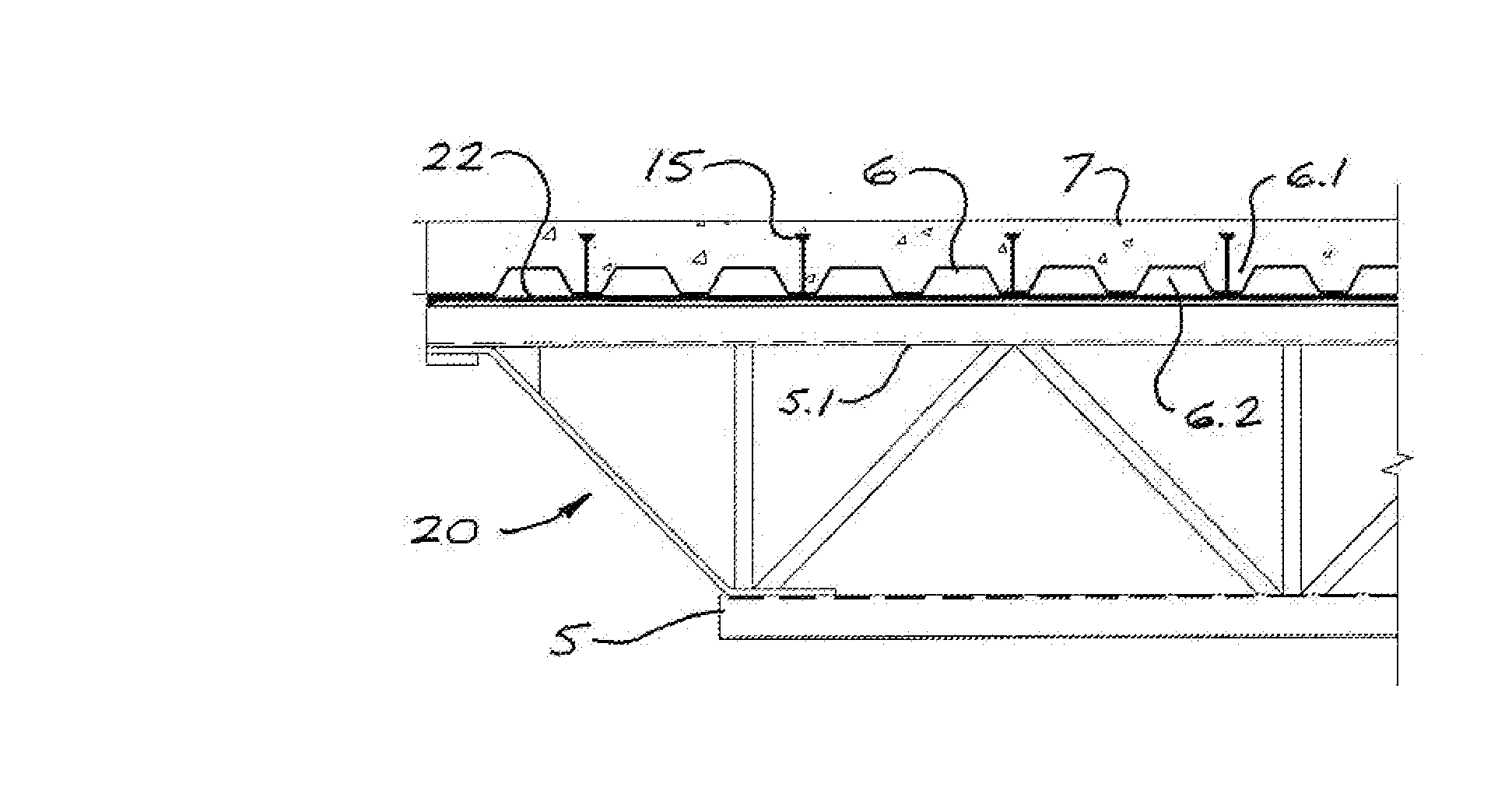
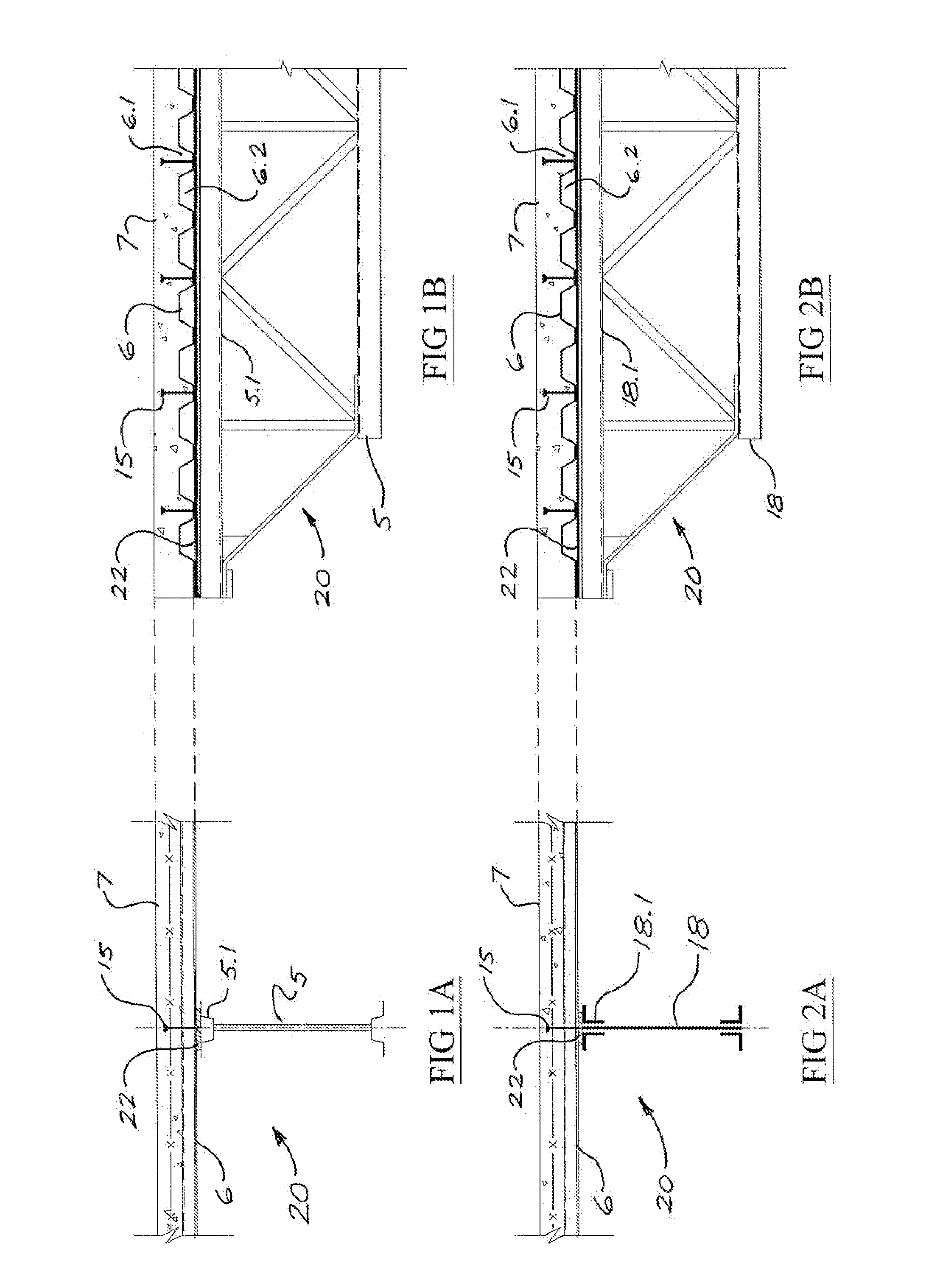
[0093]FIGS. 1A and 1B illustrate a shear-connection-ready open-web steel joist 20 (SCR-OWSJ) in accordance with one embodiment of the present invention. SCR-OWSJ 20 comprises a conventional OWSJ 5 with an elongate and substantially continuous cap plate 22 welded to the top surface of the top chord 5.1 of OWSJ 5. The substantial continuity of cap plate 22 allows corrugated steel deck 6 to be run continuous over SCR-OWSJ 20, with no need to cut deck 6 at joist locations and thus no need for deck-supporting shelf angles. At the same time, cap plate 22 provides a structural element to which shear connectors 15 can be welded (or otherwise attached) after steel deck 6 is in place, with the shear connectors 15 being positioned in selected lower flutes 6.1 of deck 6 as shown in FIG. 1B, and preferably in the plane of the associated SCR-OWSJ 20. Concrete can then be poured over the deck to form a floor slab 7, while at the same time encasing shear connectors 15 to achieve composite structura...

embodiment 3

Exterior Load-Bearing Wall

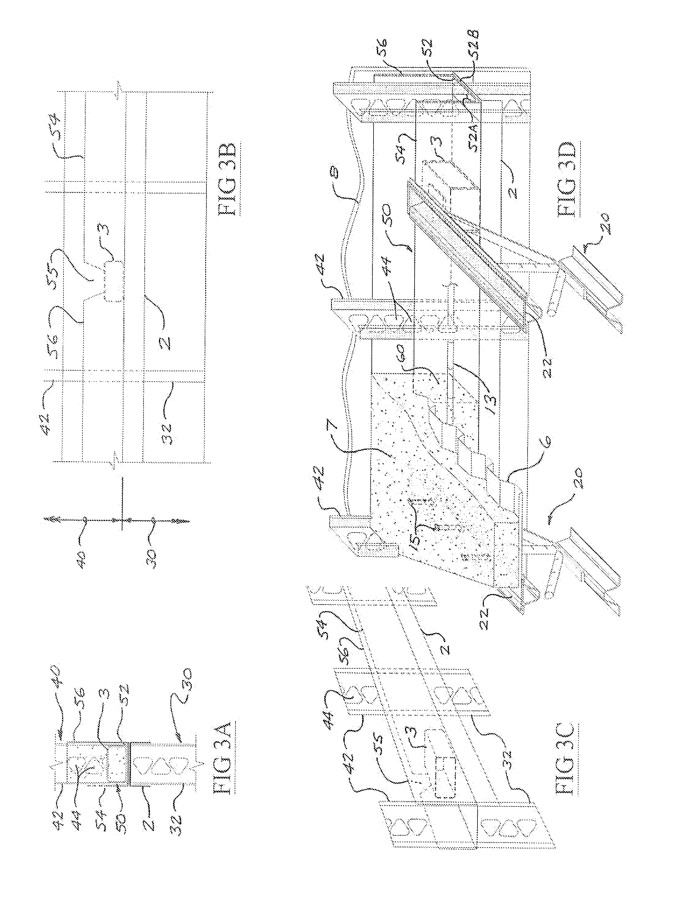
[0096]FIGS. 3A, 3B, 3C, and 3D illustrate details of a floor-to-wall connection in accordance with the present invention (Embodiment 3), wherein an exterior light-gauge steel-stud load-bearing (LBW) wall 30 supports a “concrete-topped steel-deck-on-SCR-OWSJ” floor system. Lower LBW 30 comprises a plurality of light-gauge steel studs 32 extending between a light-gauge steel top track 2 and a bottom track (not shown). An upper LBW 40 comprises: [0097] a light-gauge steel top track41 (not shown); [0098] an U-shaped light-gauge steel base track 50, comprising a continuous web member 52 having an inner face 52A and an outer face 52B, a continuous inner flange 54, and a continuous outer flange 56, with: [0099] inner flange 54 and outer flange 56 being parallel and extending substantially perpendicularly from inner face 52A of web 52; [0100] inner flange 54 having a plurality of cutouts 55, each shaped to receive a structural joist; and [0101] base track 50 being ...

embodiment 4

Interior LBW

[0109]FIGS. 4A, 4B, 4C, and 4D illustrate details for a variant (Embodiment 4) largely similar to that shown in FIGS. 3A, 3B, 3C, and 3D, but at an interior load-bearing wall supporting SCR-OWSJs 20 from both sides of the wall. The main difference is that Embodiment 4 uses a base track 50′ generally similar to base track 50 shown in FIGS. 3A, 3B, 3C, and 3D, but having both two equal-height flanges 54′ each having joist cutouts 55 and terminating at the underside of steel deck 6. Steel deck 6 is stopped on each either side of base track 50′ to allow concrete to flow into base track 50′ and thus form a T-beam 60′ integral with floor slab 7 (analogous to the spandrel beam 60 spandrel beam 60 of Embodiment 3). Other construction details will be the same as described in connection with FIGS. 3A, 3B, 3C, and 3D.

[0110] Although Embodiment 4 has been illustrated and described in association with the use of SCR-OWSJs 20, it will be appreciated that the system can be readily ada...


PUM


Abstract

A joist-and-deck floor construction system uses open-web steel joists (OWSJ) having continuous top-chord cap plates to facilitate continuous placement of corrugated steel deck over the OWSJs and to allow shear connectors to be field-applied to the cap plates, through the lower flutes of the deck, to achieve composite structural action between the OWSJ and a concrete floor slab poured over the deck. A composite steel stud wall construction system has a bottom track perforated to receive reinforcing dowels projecting from a concrete support element, such that infill concrete may be placed to a desired height within the stud assembly to give the lower ends of the studs a significant degree of structural fixity. The stud wall can also be constructed on top of steel floor deck, prior to placement of floor concrete.

Description

CROSS-REFERENCE TO RELATED APPLICATIONS [0001] This application is a continuation-in-part, pursuant to 35 U.S.C. 120, of U.S. patent application Ser. No. 11 / 112,911, filed on Apr. 25,2005, and the specification of said earlier application is incorporated herein by reference in its entirety.FIELD OF THE INVENTION [0002] The present invention relates to floor and wall construction methods and systems using steel floor and wall framing members, and relates in particular to composite floor construction using steel joists supporting concrete-topped decking in conjunction with composite steel beams and wall construction systems using light-gauge steel stud framing members. BACKGROUND OF THE INVENTION Load-Bearing Wall Construction [0003] In conventional construction of multi-storey structures comprising load-bearing walls, platform framing technique is used. As the name suggests, platform framing relies on the floor assembly to provide a platform for subsequent framing construction. The ...

Claims


Application Information

Patent Timeline
IPC IPC(8): E04B1/20
CPCE04B1/24E04B5/10E04B5/40E04C5/065E04B2001/2484E04C3/083E04C5/0645E04B2001/2481
Inventor SIU, WILFRED W.
Owner SIU WILFRED W
Why Eureka
Try Eureka