Thermoelectric conversion device and manufacture method of the same

a technology of thermal conversion device and manufacture method, which is applied in the manufacture/treatment of thermal devices, semiconductor devices, electrical apparatus, etc., can solve the problems of deterioration of air-blowing capacity of air-blowing system, and so as to reduce the deterioration of heat-exchange capacity due to thick film and reduce the deterioration of heat-exchange capacity

Inactive Publication Date: 2008-01-03
DENSO CORP
View PDF9 Cites 28 Cited by
  • Summary
  • Abstract
  • Description
  • Claims
  • Application Information

AI Technical Summary

Benefits of technology

[0014]Because the insulating film having the predetermined thickness can be formed, the deterioration of an air-blowing capacity of an air blowing system and the deterioration of a heat-exchanging capacity due to the thick film can be reduced.
[0016]Furthermore, because the insulating film is readily formed at the joining portion between the thermoelectric element and the heat exchanging member, migration can be restricted.
[0019]In this case, for the thermoelectric element module where the thermoelectric elements and the heat exchanging members are arrayed at the multiple rows with respect to the flow direction of the heat transfer media, the insulating film can be evenly formed at the thermoelectric elements and the heat exchanging members which are arranged at the rows of the inner side. Thus, the deterioration of an air-blowing capacity of an air blowing system and the deterioration of a heat-exchanging capacity due to the thick film can be reduced.
[0020]Moreover, in the immersion process, the insulating material is applied by applying the predetermined voltage to the assembly of the thermoelectric element module and the heat exchanging members, so that the insulating film having the even thickness can be formed at the current-carrying part of the thermoelectric element module. Furthermore, because the film having a thickness larger than a necessary value is reduced, the film stretching can be restricted from occurring at a narrow gap.
[0021]Furthermore, because the insulating film is readily formed at the joining portion between the thermoelectric element and the heat exchanging member, migration can be restricted.

Problems solved by technology

Therefore, the heat exchanging capacity will be deteriorated due to the increase of the heat resistance because of the thick film.
Moreover, there will occur film stretching or the like at the narrow gap, so that the air-blowing resistance of an air blowing passage of an air blowing system will increase and the air-blowing capacity of the air blowing system will be deteriorated.
Therefore, a variation in the wind velocity and that in the temperature are caused, so that the heat-exchanging capacity is deteriorated.
Thus, in this case, it is difficult to form the insulating film at the thermoelectric elements and the heat exchanging members which are arranged at the row of the inner side.

Method used


Image

  • Thermoelectric conversion device and manufacture method of the same
  • Thermoelectric conversion device and manufacture method of the same
  • Thermoelectric conversion device and manufacture method of the same

Examples


embodiments

First Embodiment

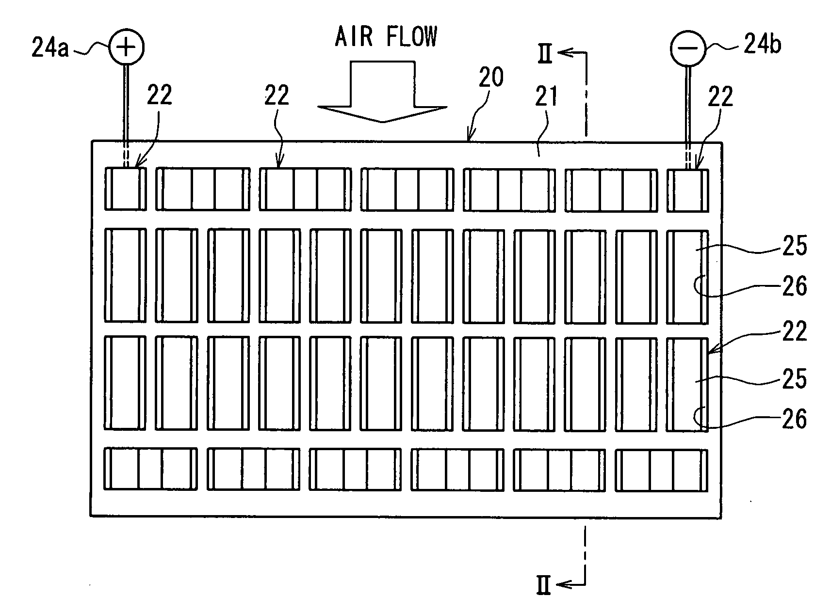
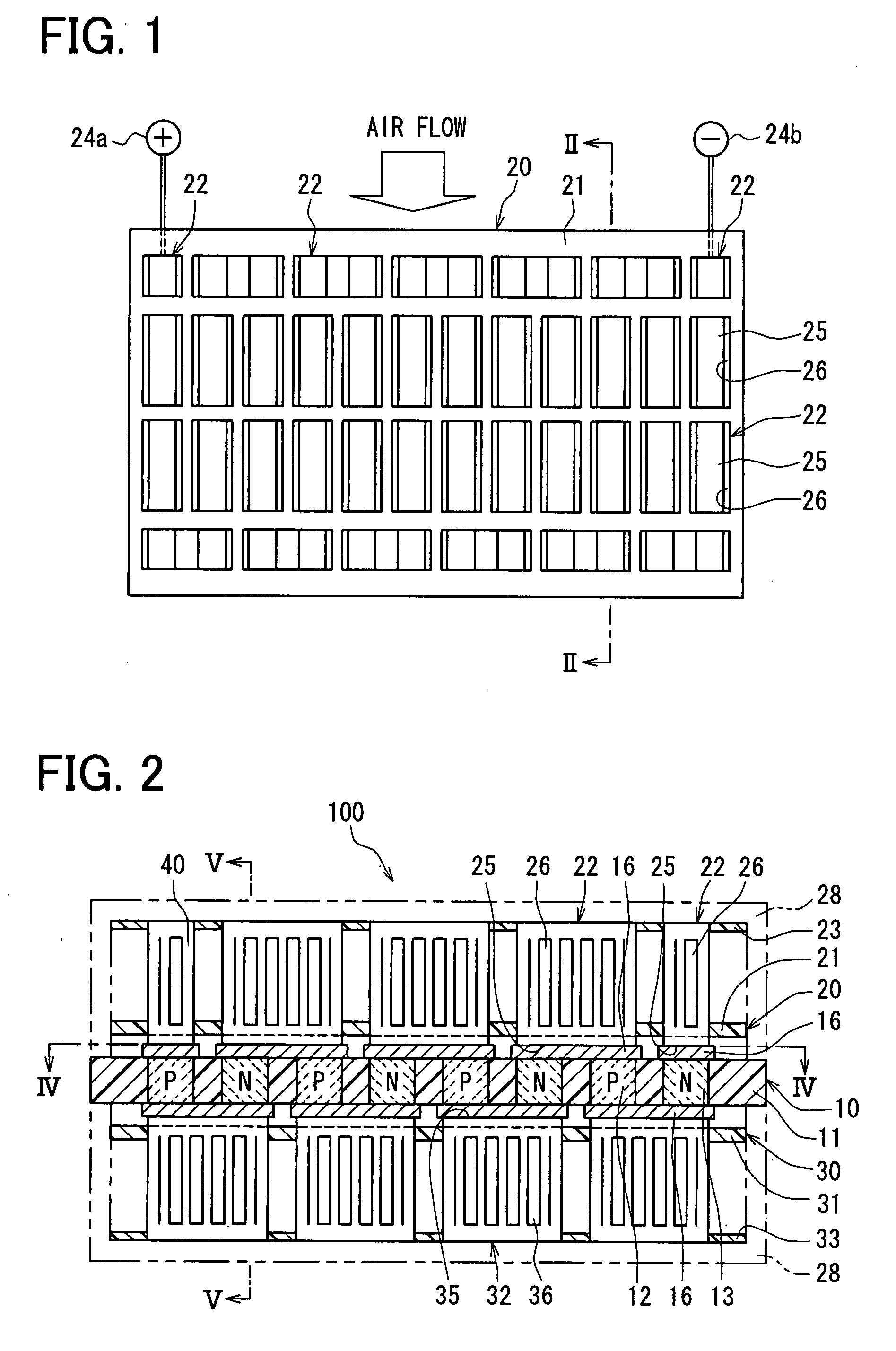
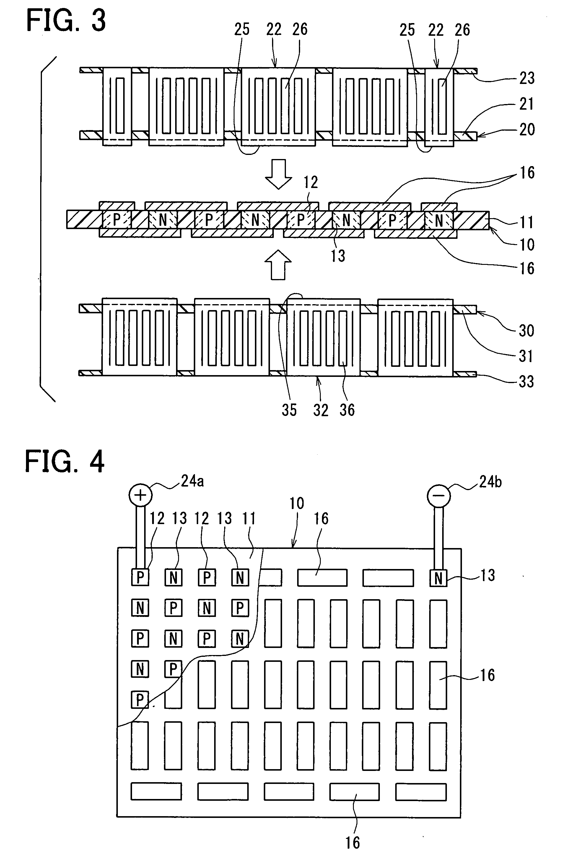
[0044]A thermoelectric conversion device 100 according to a first embodiment of the present invention will be described with reference to FIGS. 1-8. The thermoelectric conversion device 100 can be suitably used for a cooling device or a heating device. For example, the thermoelectric conversion device 100 can be suitably used in a seat air-conditioning device mounted at a vehicle. In this case, each of a sitting portion and a back portion of a seat of the vehicle can be provided with the thermoelectric conversion device 100, so that cool air cooled by the thermoelectric conversion device 100 can be blown outward from the surface of the seat. It is desirable for the thermoelectric conversion device 100 to be small-sized to be mounted in the vehicle seat where the mounting space is narrow.

[0045]As shown in FIGS. 1-5, the thermoelectric conversion device 100 is provided with a thermoelectric element substrate unit 10 (thermoelectric element module), a first fin board un...

second embodiment

[0109]A second embodiment of the present invention will be described with reference to FIGS. 9-11. In this embodiment, the electrode members 16 in the thermoelectric conversion device 100 are omitted.

[0110]According to the second embodiment, the heat-absorbing electrode portion 25 of the heat exchanging member 22 and the heat-radiating electrode portion 35 of the heat exchanging member 32 double as the electrode member. In this case, the electrode portion 25 (35) directly contacts the pair of the thermoelectric elements 12 and 13 which are arrayed at the insulating substrate 11 and are adjacent to each other, to be electrically connected in series with the thermoelectric elements 12 and 13.

[0111]Specifically, the heat-absorbing electrode portion 25 which is arranged at the upper side constructs the electrode through which the current flows from the thermoelectric element 13 to the thermoelectric element 12 (adjacent to this thermoelectric element 13), the heat-radiating electrode po...

third embodiment

[0115]A third embodiment of the present invention will be described with reference to FIGS. 12-17.

[0116]As shown in FIG. 12, the thermoelectric conversion device 100 includes a thermoelectric conversion module 200 which is provided with the thermoelectric element substrate unit 10, the first fin board unit 20 and the second fin board unit 30, and the case members 28 and 38 in where the thermoelectric conversion module 200 is accommodated.

[0117]With reference to FIGS. 12-15, the thermoelectric element substrate unit 10 has the multiple p-type thermoelectric elements 12 and the multiple N-type thermoelectric elements 13, and the insulating substrate 11 (holding member) which are integrated with each other. Specifically, the multiple engagement holes are arranged in the pattern of substantial lattice of uniform squares, at the insulating substrate 11 made of the insulating material (for example, glass epoxy, phenol resin, PPS resin, LCP resin or PET resin) having a plate shape. The mul...


PUM


Abstract

A thermoelectric conversion device and a manufacture method for the thermoelectric conversion device are provided. The manufacture method includes a joining process for respectively joining heat exchanging members to thermoelectric-element pairs of an thermoelectric element module, an immersion process for immersing the thermoelectric element module and the heat exchanging members in an immersion sink where an melted insulating material is provided, and a baking process for baking an assembly of the thermoelectric element module and the heat exchanging members where the insulating material has been applied in the immersion process so that an insulating film is formed. Thus, an electrical insulation can be provided while a heat-exchanging capacity and an air-blowing capacity are maintained.

Description

CROSS REFERENCE TO RELATED APPLICATION[0001]This application is based on a Japanese, Patent Application No. 2006-178307 filed on Jun. 28, 2006, a Japanese Patent Application No. 2006-181101 filed on Jun. 30, 2006 and a Japanese Patent Application No. 2007-19951 filed on Jan. 30, 2007, the disclosures of which are incorporated herein by reference.FIELD OF THE INVENTION[0002]The present invention relates to a thermoelectric conversion device and a manufacture method of the same.BACKGROUND OF THE INVENTION[0003]Generally, with reference to JP-2006-114840A, a thermoelectric, conversion device is provided with a thermoelectric element substrate and multiple heat exchanging members. Multiple thermoelectric-element pairs, each of which includes a P-type thermoelectric element and a N-type thermoelectric element, are arrayed at the thermoelectric element substrate. All of the thermoelectric elements are electrically connected with each other. The heat exchanging members are respectively pro...

Claims


Application Information

Patent Timeline
Patent Type & Authority Applications(United States)
IPC IPC(8): H01L35/32H01L35/34
CPCH01L35/30H01L35/32H01L35/34H01L2924/0002H01L2924/00H10N10/13H10N10/01H10N10/17
Inventor KUROYANAGI, ISAOMATSUOKA, AKIONIMURA, KEIZOUNISHIYA, SHINSUGAWARA, HIROYOSHIITO, YUJINIIMI, YASUHIKO
Owner DENSO CORP
Why Eureka
Try Eureka