Hose for Introduction and Distribution of Inflator Gas

Inactive Publication Date: 2008-01-03
TOYO TOYOBO CO LTD +1
View PDF4 Cites 7 Cited by
  • Summary
  • Abstract
  • Description
  • Claims
  • Application Information

AI Technical Summary

Benefits of technology

[0018] In the hose for introduction and distribution of inflator gas according to the present invention, improvement in folding property and weight reduction are attempted while durability to the

Problems solved by technology

In those proposals however, although there are descriptions that an auxiliary cloth is utilized for prevention of breakage of an air bag cushion itself by a high-pressure gas from an inflator and that flow of the gas is controlled, there is no specific consideration at all for characteristics of a hose (sometimes such a hose is called as “a liner tube” or “an inner tube”).
Therefore, in a hose for introduction and distribution of inflator gas, it is also an important issue to ensure a high folding property.
Thus, there are problems that, for example, a gas distributing hole portion is deformed due to its burst by pressure of the inflator gas whereby inflated shape of an air bag upon deployment becomes non-uniform and that fiber near the gas introducing opening is cut and scattered into the air bag and melted resulting in breakage of the air bag cushion itself.
However, when the fiber is made thick, bulk becomes high causing a problem in a storing property and restriction in interior design of a car and that is a problem while a highly strong fiber is expensive and, when it is used, cost becomes high and that is a problem in view of practical use.
Further, in passenge

Method used

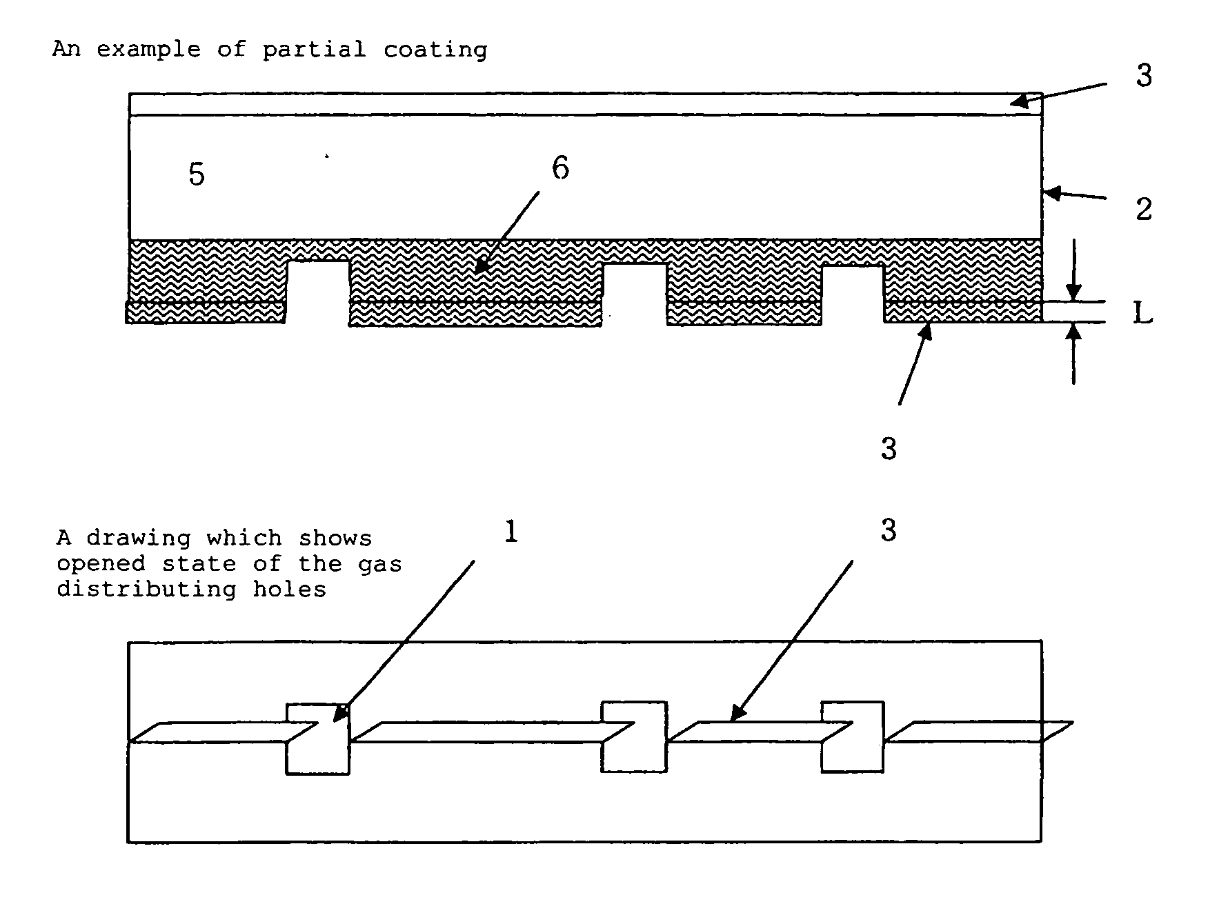
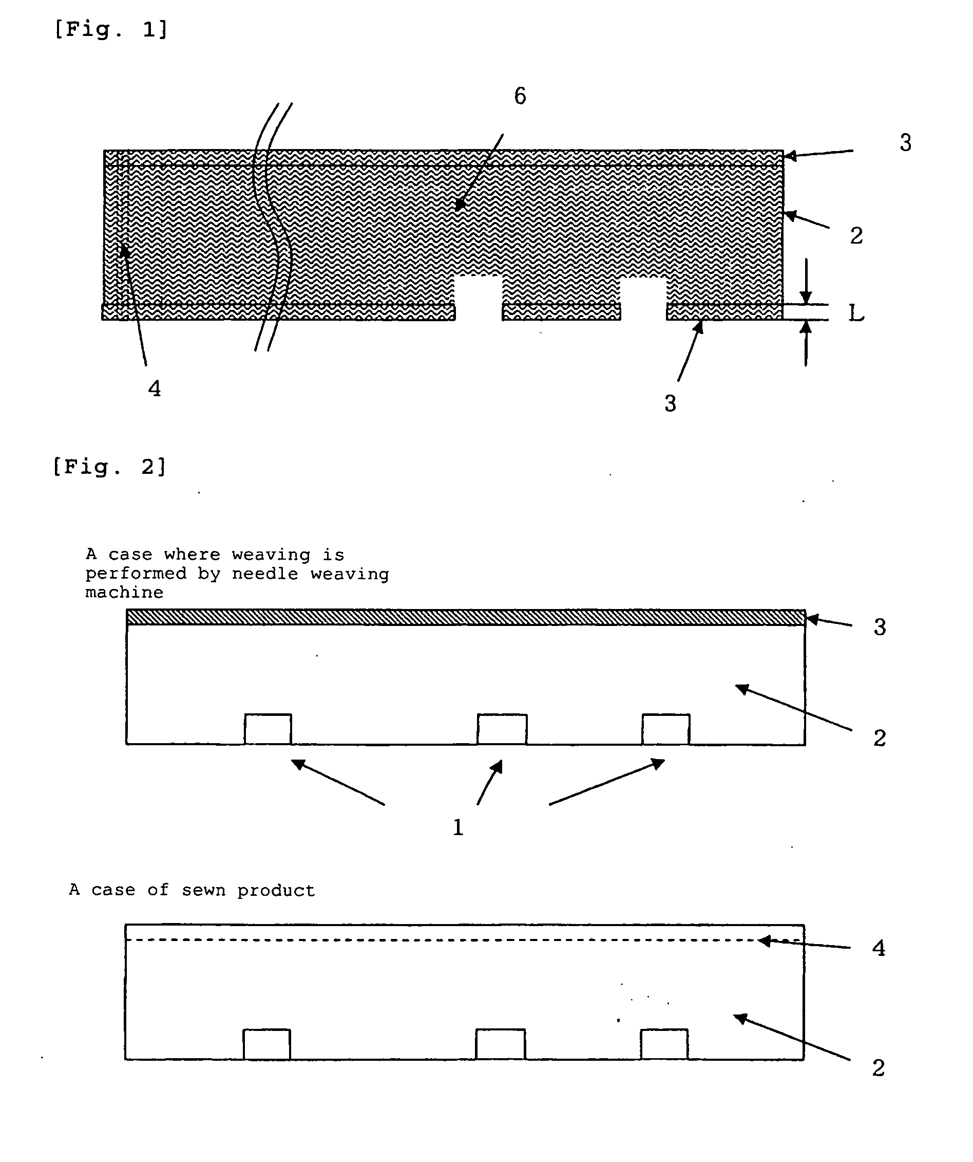
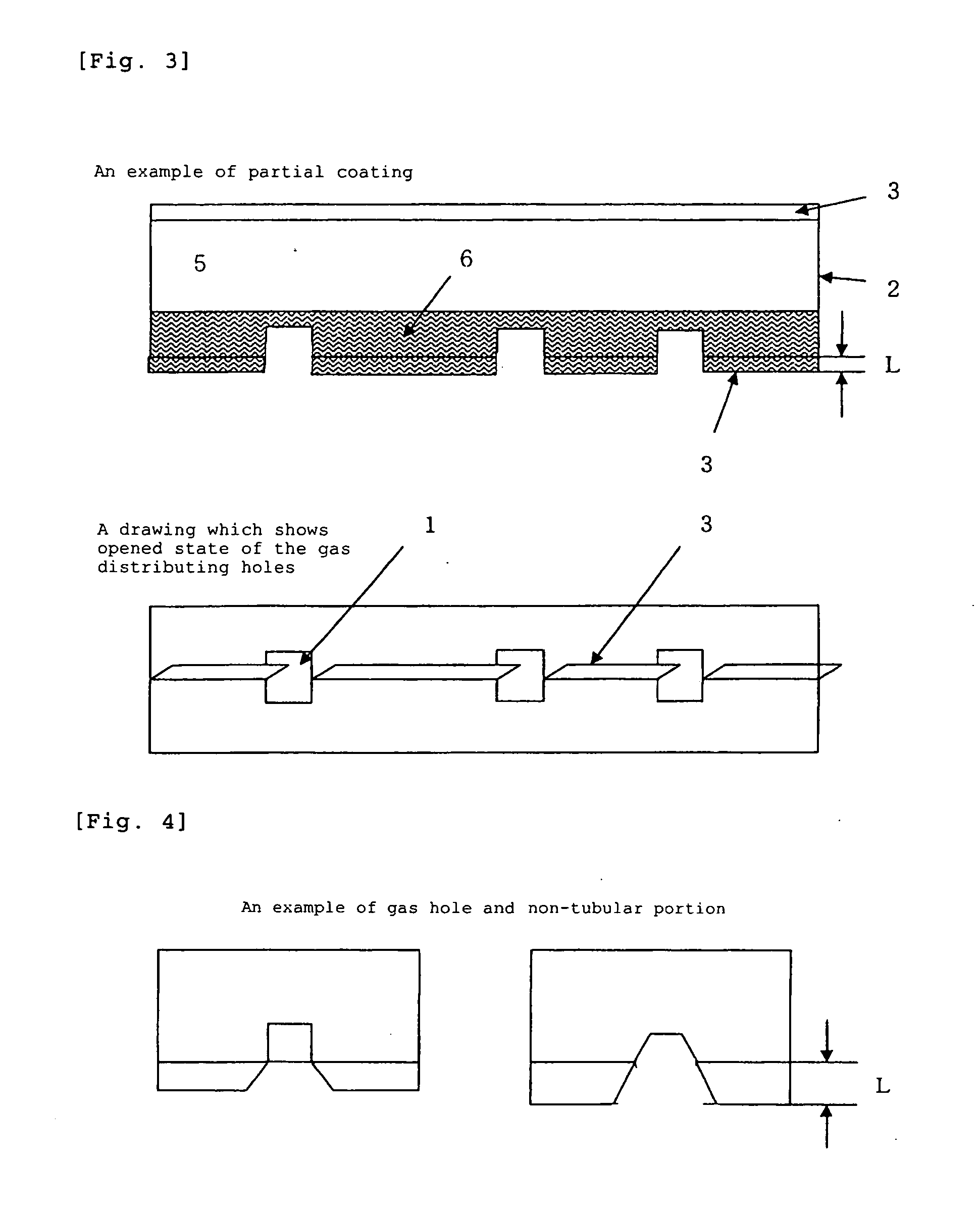

Image

  • Hose for Introduction and Distribution of Inflator Gas
  • Hose for Introduction and Distribution of Inflator Gas
  • Hose for Introduction and Distribution of Inflator Gas

Examples


experimental example 1

[0079] A jacket (tube-shaped woven fabric before coating) was woven by a hollow weaving using a water-jet weaving machine equipped with dobby. The filament used was polyamide 66 fiber with a tenacity of 8.1 cN / dtex where warp was 470 dtex / 72 f and weft was 470 dtex / 72 f in which single yarn of both had around cross section. After that, the product was subjected to a washing step at 95° C. and to a drying / setting step at 180° C. to give a woven fabric where 16 rows of tubular-shaped woven products were aligned in parallel in a warp direction so as to make tubular portion width 68 mm, interval with the adjacent tubular portion (hereinafter, referred to as non-tubular portion) 30 mm and total width 160 cm. Weaving density and CF of the tubular portion are shown in Table 1.

[0080] Both sides of the resulting broad-width multi-row-woven fabric were applied with a coating agent (silicone resin: “Elastosil LR 6200” manufactured by Wacker) containing an additive (“Adhesion Promoter HF86” ma...

experimental example 2

[0081] The same operation as in Experimental Example 1 was carried out to give a woven fabric except the use of polyamide 66 fiber with a tenacity of 8.0 cN / dtex where warp was 470 dtex / 72 f and weft was 470 dtex / 72 f in which single yarn of both had a nearly elliptic cross-section and degree of flatness (long diameter / short diameter) was 3.0. The result is shown in Table 1.

experimental example 3

[0082] A jacket (tube-shaped woven fabric before coating) was woven by a hollow weaving using a Rapier weaving machine equipped with dobby. The filament used was polyamide 66 fiber with a tenacity of 8.1 cN / dtex where warp was 470 dtex / 144 f and weft was 470 dtex / 144 f in which single yarn of both had a round cross section. After that, the product was subjected to a washing step at 95° C. and to a drying / setting step at 180° C. to give a woven fabric where 16 rows of tubular-shaped woven products were aligned in parallel in a warp direction so as to make tubular portion width 68 mm, interval with the adjacent tubular portion (hereinafter, referred to as non-tubular portion) 30 mm and total width 160 cm. Weaving density and CF of the tubular portion are shown in Table 1.

[0083] The resulting broad-width multi-row-woven fabric was subjected to a heat cutting at the part which is 15 mm from the boundary of the tubular portion in parallel to the warp with the full length of 2 m to prepa...


PUM


Abstract

A reliable hose for introduction and distribution of inflator gas improves the storing properties of an air bag device for side collision, reduces storing space, is advantageous in terms of cost, and has enough strength. A hose made of woven fabric for introduction and distribution of inflator gas is arranged in an air bag device for side collision and has one or more distributing hole(s) for introduction and distribution of gas from an inflator to the inner area of an air bag upon actuation of the air bag. On the side containing said distributing hole, there is a non-tubular portion which projects from a hose tubular portion to the outside of an opposite side to the tubular portion.

Description

REFERENCE TO RELATED APPLICATIONS [0001] This application is a national stage application under 35 USC 371 of International Application No. PCT / JP2005 / 008586, filed May 11, 2005, which claims priority from Japanese patent application No. 2004-143658, filed May 13, 2004, the disclosures of which are incorporated herein by reference.TECHNICAL FIELD OF THE INVENTION [0002] The present invention relates to the parts for an air bag device for side collision whereby persons in the car are protected upon side collision of cars and, more particularly, it relates to a hose for introduction and distribution of inflator gas which is optimum for introduction of inflator gas into the above air bag. BACKGROUND ART [0003] In a driver's seat, a passenger's seat, etc., air bag devices which inflate an air bag upon collision of cars to protect the persons in the car are installed. Such an air bag device is constituted from an inflator which is a gas-generating device, an air bag which is inflated by ...

Claims


Application Information

Patent Timeline
IPC IPC(8): B60R21/26B60R21/21B60R21/16B60R21/233B60R21/2346D03D1/02D03D3/02
CPCB60R21/26B60R21/2346
Inventor KONISHI, TATSUO
Owner TOYO TOYOBO CO LTD
Why Eureka
Try Eureka