Motor Generator and Automobile Carrying the Same

a motor generator and stator technology, applied in the direction of electric propulsion mounting, magnetic circuit characterised by magnetic materials, shape/form/construction, etc., can solve the problems of difficult to reduce the total axis length including the winding, the possibility of reducing the body size is limited, and the motor generator is difficult to mount the stator. , to achieve the effect of a wide range of output performance, simple and low-cost molding process, and superior mountability

Active Publication Date: 2008-01-03
KAISHA TOYOTA MOTORS KABUSHIKI
View PDF7 Cites 16 Cited by
  • Summary
  • Abstract
  • Description
  • Claims
  • Application Information

AI Technical Summary

Benefits of technology

[0033] According to the present invention, because the the yoke part of the stator protrudes from the teeth part towards an outside along the axial direction, a compact and high-power motor generator that exhibits superior mountability after the coil is wound can be realized.
[0034] Further, when the stator core is formed of a plurality of the magnetic dust cores joined to each other along the axial direction, a motor generator having a broader range of output performances can be realized by way of a simple and low-cost molding process.

Problems solved by technology

Accordingly, mountability of motor generators comprising the stator is problematic.
Accordingly, the possibility of reducing body sizes has been limited.
Still further, because the axial length of the stator is increased due to the protruded coil end part in the conventional stator structure, it has been difficult to downsize the total axis length including the winding 52.

Method used


Image

  • Motor Generator and Automobile Carrying the Same
  • Motor Generator and Automobile Carrying the Same
  • Motor Generator and Automobile Carrying the Same

Examples


Embodiment Construction

[0049] Referring to drawings, preferred embodiments of the present invention will be described in detail bellow. It should be noted that identical reference characters in the drawings represent identical or equivalent components.

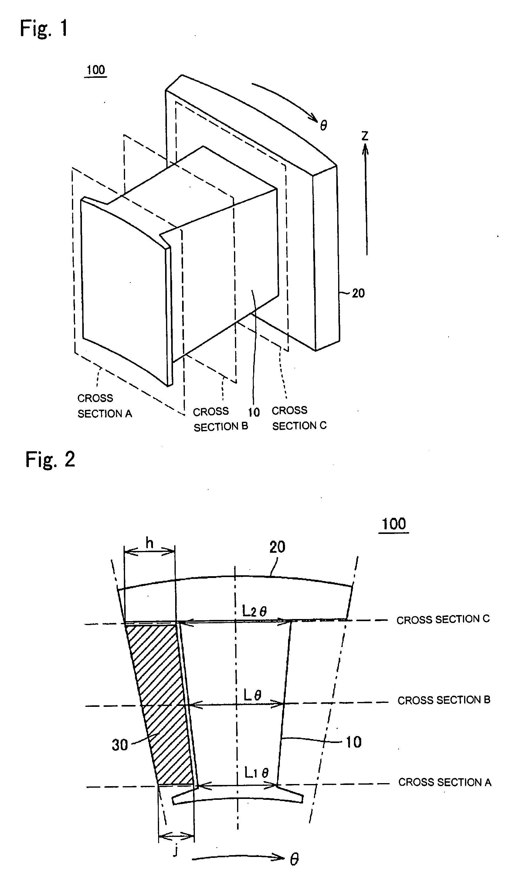
[0050]FIG. 1 is a perspective view showing one pole of a stator core in a stator of a motor generator according to an embodiment of this invention. Although it is not illustrated, the stator core is, on the whole, formed in a hollow cylindrical shape in which a number, which is equal to the number of poles of a motor generator, of poles of the stator core 100 in FIG. 1 are annularly arranged. Further, the stator core includes an annular yoke part, a teeth part having a predetermined number of teeth arranged in an annular form on an inner circumference side of the yoke part so as to direct to a radial inside, and a predetermined number of slots formed between adjacent teeth and extending along the axial direction. The numbers of the teeth and the slots match...


PUM


Abstract

In a stator core composed of a powder compacted magnetic body, a yoke part comprises a protrusion protruding from an axial end face of a tooth. The tooth has an axial length gradually decreases towards an outside along the radial direction of the stator core, and a circumferential length which gradually increases towards an outside along the radial direction of the stator core. In one of the cross sections of stator core perpendicular to a radial direction, the height difference between axial end faces of the yoke part and the tooth is substantially equal to an axial length of a coil end part. Further, a cross-sectional area of the tooth perpendicular to the radial direction is substantially maintained constant along the radial direction, and the cross-sectional area is secured at a junction between the tooth and the yoke part, while half of the cross-sectional area is secured in a circumferential cross section of the yoke part.

Description

[0001] This is a 371 application of PCT / JP2005 / 020257 filed on 28 Oct. 2005, claiming priority to Japanese Applications No. 2004-316363 filed on 29 Oct. 2004 and No. 2005-126715 filed 25 Apr. 2005, the contents of which are incorporated herein by reference.FIELD OF THE INVENTION [0002] The present invention relates to a motor generator composed of a stationary part (hereinafter also referred to as a stator) and a rotating part (hereinafter also referred to as a rotor) and an automobile having the motor generator mounted therein, and, more particularly, to a stator of a motor generator. BACKGROUND OF THE INVENTION [0003] In a motor generator composed of a stator and a rotor, the stator consists of a stator core having a plurality of slots formed thereto, and coils wound around comb teeth (hereinafter also referred to simply as “teeth”) formed between the slots. On the other hand, the rotor consists of a rotor core, magnets bearing magnetic force, and a shaft working as an axis of rot...

Claims


Application Information

Patent Timeline
Patent Type & Authority Applications(United States)
IPC IPC(8): H02K1/14H02K1/02H02K1/18
CPCH02K1/08H02K15/022H02K3/522H02K1/148
Inventor ENDO, YASUHIROMIZUTANI, RYOJITATEMATSU, KAZUTAKAHARADA, KENJIYAMAGUCHI, TOSHIYAHOSHINA, EISUKE
Owner KAISHA TOYOTA MOTORS KABUSHIKI
Why Eureka
Try Eureka