Color conversion substrate and color display

a color conversion substrate and color display technology, applied in the direction of discharge tube luminescnet screens, instruments, semiconductor/solid-state device details, etc., can solve the problems of low patterning accuracy of the thick shielding layer, unnecessary fluorescence emitted, and difficulty in obtaining a high-definition color conversion substrate and a high-definition color display, etc., to achieve excellent color reproducibility and low cost

Inactive Publication Date: 2008-01-03
IDEMITSU KOSAN CO LTD
View PDF4 Cites 88 Cited by
  • Summary
  • Abstract
  • Description
  • Claims
  • Application Information

AI Technical Summary

Benefits of technology

[0024]According to the invention, there can be provided a high-resolution color conversion substrate and a color display which exhibits excellent

Problems solved by technology

However, since the patterning accuracy of the thick shielding layer is low, only a rough pattern (aspect ratio (thickness/width)=½) can be formed.
Therefore, it is difficult to obtain a high-definition color conversion substrate and a high-definition color display.
However, since the partition wall is transparent, isotropic fluorescence from the fluorescence conversion layer enters the adjacent fluorescence conversion layer through the side surface of the partition wall to excite the adjacent fluorescence conversion layer, whereby unnecessary fluorescence is emitted.
This causes the colors to be mixed, whereby a color display with high color reproducibility is hindered.
Moreover, sin

Method used


Image

  • Color conversion substrate and color display
  • Color conversion substrate and color display
  • Color conversion substrate and color display

Examples


first embodiment

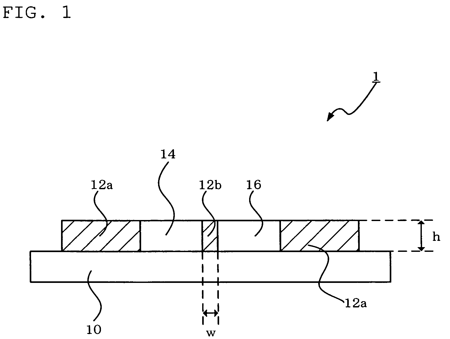
[0036]FIG. 1 is a schematic cross-sectional view showing one embodiment of the color conversion substrate according to the invention.

[0037]A color conversion substrate 1 includes blue color filter layers 12a and 12b, a green fluorescence conversion layer 14, and a red fluorescence conversion layer 16 on a transparent substrate 10. The blue color filter layer 12b separates the green fluorescence conversion layer 14 and the red fluorescence conversion layer 16. The blue color filter layer 12a may form a blue pixel, the green fluorescence conversion layer 14 may form a green pixel, and the red fluorescence conversion layer may form a red pixel. In FIG. 1, h indicates the thickness of the blue color filter layers 12a and 12b, and w indicates the width of the blue color filter layer 12b which separates the fluorescence conversion layers. FIG. 1 illustrates one green fluorescence conversion layer 14 and one red fluorescence conversion layer 16. Note that the blue color filter layer 12a, t...

second embodiment

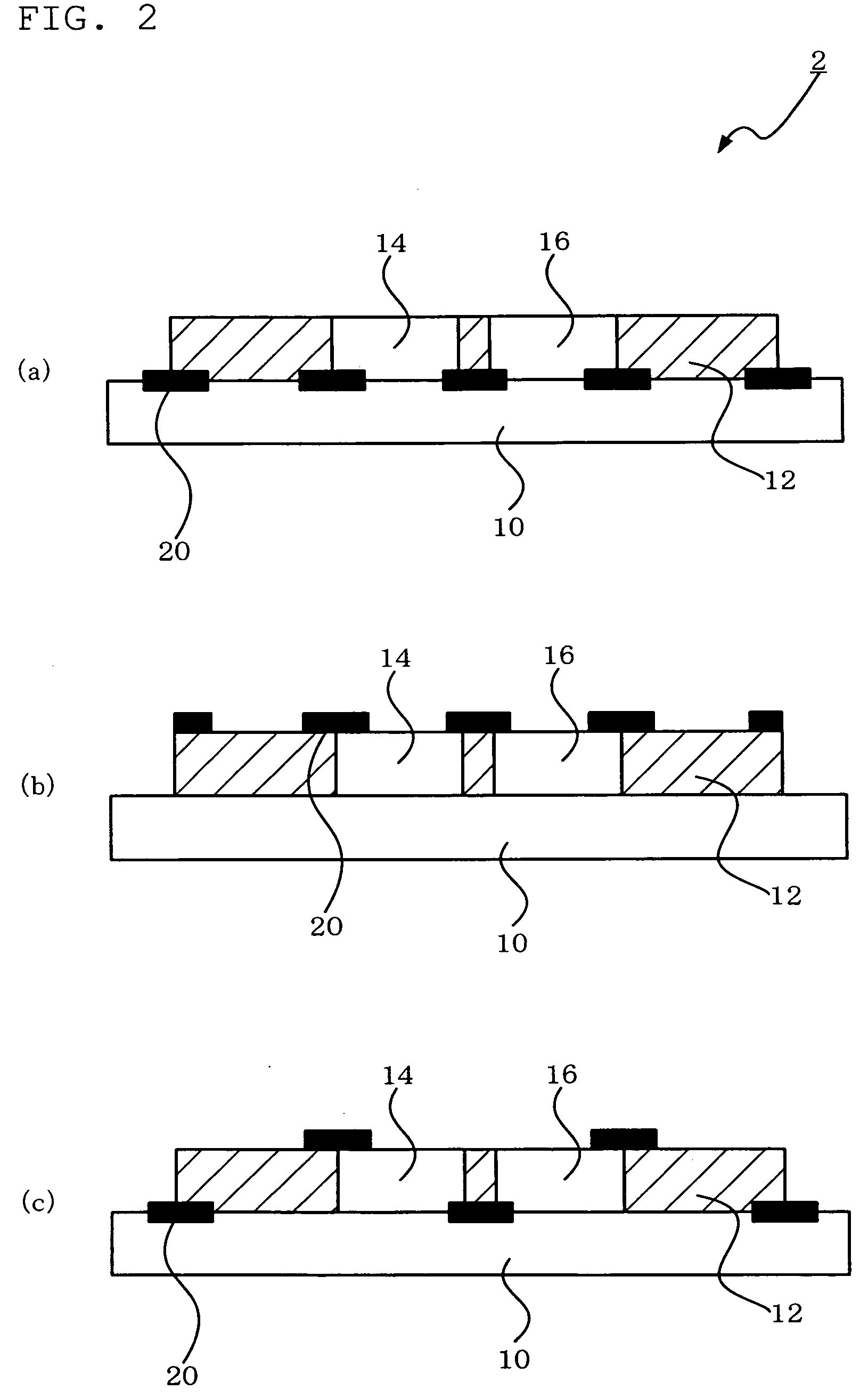
[0045]FIG. 2 is a schematic cross-sectional view showing another embodiment of the color conversion substrate according to the invention.

[0046]In a color conversion substrate 2, black matrixes 20 are respectively provided between the blue color filter layer 12a, the green fluorescence conversion layer 14, and the red fluorescence conversion layer 16 in the above-described color conversion substrate 1 according to the first embodiment. Since incidence and reflection of external light can be reduced by forming the black matrixes 20, visibility such as contrast and viewing angle characteristics can be improved when forming a color display. As the black matrix 20, a black matrix having a small thickness while maintaining light-shielding properties is preferable.

[0047]It suffices that the black matrixes 20 be respectively provided between the blue color filter layer 12a, the green fluorescence conversion layer 14, and the red fluorescence conversion layer 16. The black matrixes 20 may be...

third embodiment

[0048]FIG. 3 is a schematic cross-sectional view showing yet another embodiment of the color conversion substrate according to the invention.

[0049]In a color conversion substrate 3, as shown in FIG. 3(a), color filters 30 are respectively formed between the green fluorescence conversion layer 14 and the transparent substrate 10 and between the red fluorescence conversion layer 16 and the transparent substrate 12 in the above-described color conversion substrate 1 according to the first embodiment. Since luminescence of the fluorescence conversion layers 14 and 16 due to external light can be reduced by forming the color filter 30, contrast is increased when forming a color display. Moreover, the chromatic purity of fluorescence emitted from the fluorescence conversion layers 14 and 16 and outcoupled to the outside can be improved. As shown in FIG. 3(b), the black matrixes 20 may be additionally formed.


PUM


Abstract

A color conversion substrate including a transparent substrate; and a plurality of blue color filter layers and a plurality of fluorescence conversion layers provided on the transparent substrate; part of the blue color filter layers separating the fluorescence conversion layers.

Description

TECHNICAL FIELD[0001]The invention relates to a color conversion substrate, a method for producing the same, and an color display using the same. In particular, the invention relates to a color conversion substrate wherein a blue color filter layer separates a fluorescent conversion layer.TECHNICAL BACKGROUND[0002]A technology (color conversion system) has been disclosed which converts light emitted from a blue emitting device into green light and red light using fluorescent conversion layers to emit light of blue, green, and red (i.e. three primary colors), thereby achieving a full color display (patent documents 1 to 3).[0003]A full color display can be obtained using the color conversion system by combining a single-color blue emitting device and a color conversion substrate comprising a blue color filter layer, green fluorescent conversion layer and red fluorescent conversion layer. Note that the blue color filter layer is used for enhancing a chromatic purity of light from the ...

Claims


Application Information

Patent Timeline
IPC IPC(8): H01J1/62H01J63/04
CPCG02B5/201G02B2207/113H01J29/89H01L51/5284H01J2329/89H01J2329/895H01L27/322H01J29/898H10K59/38H10K50/865H01L21/4867H01L23/145
Inventor EIDA, MITSURU
Owner IDEMITSU KOSAN CO LTD
Why Eureka
Try Eureka