Image processing device and method

a processing device and image technology, applied in the field of image processing devices, can solve the problems of color phase shift, deterioration of image quality, and decrease in processing speed, so as to improve image quality, improve processing speed, and prevent color phase shift

Inactive Publication Date: 2008-01-03
FUJIFILM CORP
View PDF3 Cites 20 Cited by
  • Summary
  • Abstract
  • Description
  • Claims
  • Application Information

AI Technical Summary

Benefits of technology

[0020]According to the present invention, the horizontal and vertical components of R, G, and B colors of each of the pixels are calculated based on the pixel data of each of the pixels and their peripheral pixels, and the colors are interpolated. Then, each of the pixels is subjected to color correction processing by performing linear matrix operation based on the horizontal and vertical components of the R, G, and B colors, and different color correction coefficients set for each of the horizontal and vertical components. Therefore, it is possible to prevent occurrence of color phase shift due to leakage of signal charges by adding weights to the color correction coefficients to such that color correction coefficients in the horizontal direction in which signal charges leak in transferring the signal charges is larger than that in the horizontal direction. It is also possible to improve processing speed since the color correction processing is performed readily.
[0021]Further, the color correction coefficients are set based on the transfer efficiency of the imaging device. Therefore, it is possible to improve the image quality by color correction processing in accordance with the transfer efficiency.

Problems solved by technology

Such a digital camera has a problem in that, due to the deterioration of transfer efficiency of the CCD image sensor, leak of charges occur between the pixels adjacent to each other at the time of being transferred, to cause color phase shift, and therefore the quality of captured image is deteriorated.
Therefore, there is a problem in that the processing speed is decreases.
Accordingly, there is a problem in that a production cost of the imaging devices increases.

Method used


Image

  • Image processing device and method
  • Image processing device and method
  • Image processing device and method

Examples


Embodiment Construction

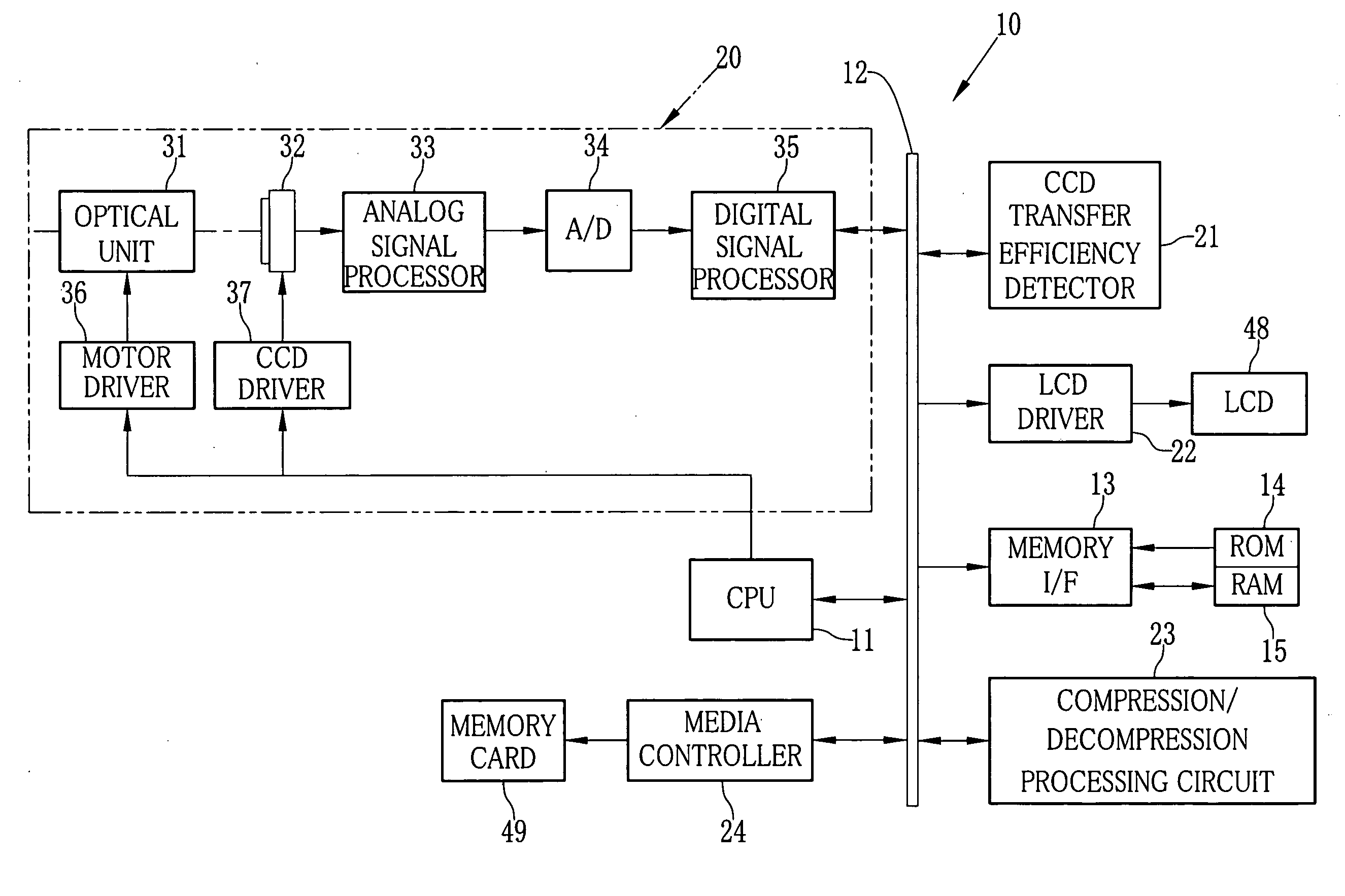
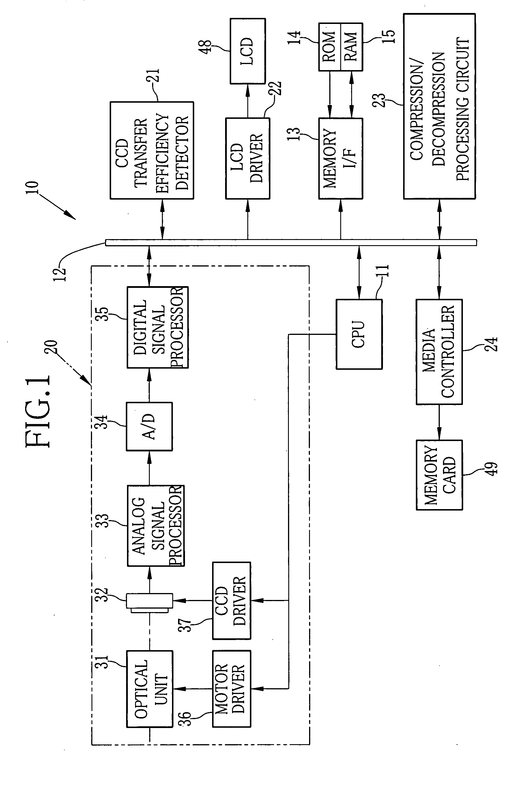
[0032]A digital camera 10 shown in FIG. 1 includes a central processing unit (CPU) 11 for controlling the operation of the camera 10. A read-only memory (ROM) 14 and a random access memory (RAM) 15 are connected to the CPU 11 via a data bus 12 and a memory interface (I / F) 13.

[0033]The ROM 14 stores a control program for controlling respective parts of the digital camera 10, various kinds of control data, information regarding transfer efficiency to be described later, and the like at the time of manufacturing the digital camera 10. The RAM 15 temporarily stores work data. The CPU 11 controls the respective parts of the digital camera 10 based on these control program and control data.

[0034]Further, in addition to the CPU 11 and the memory I / F 13, an imaging unit 20, a CCD transfer efficiency detector 21, a liquid crystal display (LCD) driver 22, a compression / decompression processing circuit 23, and a media controller 24 are connected to the data bus 12.

[0035]The imaging unit 20 is ...


PUM


Abstract

Image data of a digital signal is inputted to a digital signal processor. A CPU reads out color correction coefficients from a ROM. Weights are added to the color correction coefficients based on information regarding transfer efficiency of a CCD image sensor such that the coefficients in a horizontal direction are set larger than those in a vertical direction. Further, an interpolation processor calculates horizontal and vertical components of R, G, and B colors of each pixel through color interpolation processing based on image data of each pixel and its peripheral pixels. A linear matrix circuit is controlled by the CPU and subjects the horizontal and vertical components to linear matrix operation using the color correction coefficients, thus subjecting each pixel data to color correction processing.

Description

FIELD OF THE INVENTION[0001]The present invention relates to an image processing device for subjecting image data captured by a CCD image sensor to linear matrix processing so as to correct the color of the image, and an image processing method therefor.BACKGROUND OF THE INVENTION[0002]Recently, there is known a digital camera, which is provided with a CCD image censor and subjects image data captured by the CCD image sensor to various kinds of image processing to record the image data on a recording medium such as a memory card. Such a digital camera has a problem in that, due to the deterioration of transfer efficiency of the CCD image sensor, leak of charges occur between the pixels adjacent to each other at the time of being transferred, to cause color phase shift, and therefore the quality of captured image is deteriorated.[0003]Further, in order to solve the problem described above, there is known an invention as follows. Before image data obtained by capturing a subject by us...

Claims


Application Information

Patent Timeline
Patent Type & Authority Applications(United States)
IPC IPC(8): H04N9/73
CPCH04N5/359H04N2209/046H04N9/045H04N25/62H04N23/843H04N25/134
Inventor UEDA, TORU
Owner FUJIFILM CORP
Why Eureka
Try Eureka