High-frequency magnetic core material, its manufacturing method, and antenna including the magnetic core material

a manufacturing method and high-frequency magnetic core technology, applied in the field of magnetic core materials, can solve the problems of affecting the performance of the antenna, scattering unnecessary radio-wave noise, and leaking magnetic flux from the side face so as to achieve enhanced magnetic permeability of the magnetic core material, suppress leakage of magnetic flux, and improve dimensional accuracy

Inactive Publication Date: 2008-01-03
MITSUBISHI MATERIALS CORP
View PDF0 Cites 26 Cited by
  • Summary
  • Abstract
  • Description
  • Claims
  • Application Information

AI Technical Summary

Benefits of technology

[0026] A first effect of the invention is that the magnetic permeability of the magnetic core material can be enhanced, the dimensional accuracy can be improved, and the magnetic core material can be made hard to be damaged if thin.
[0027] This is because the magnetic core material is formed using a composite material in which a soft magnetic metal powder below a predetermined particle size and plastic or rubber are mixed together in a predetermined ratio.
[0028] Further, a second effect of the invention is that the direction dependency can be given to the magnetic permeability of the magnetic core material.
[0029] This is because, when the composite material is worked, the composite material is extended in one direction so that a soft magnetic metal powder may continue in a predetermined direction, or a direct-current magnetic field is applied to a film after the film is coated with ink in which a soft magnetic metal powder is suspended and before the coated film is dried.
[0030] Further, a third effect of the invention is that a high-performance antenna for a RFID tag or reader / writer which operates in a range of a VHF band to a UHF band can be manufactured.
[0031] This is because leakage of magnetic flux can be suppressed by using the composite material as a magnetic core of an antenna for a tag, a reader or a reader / writer of an RFID system.

Problems solved by technology

A first problem is that, since a soft magnetic ferrite has isotropy, i.e., has the same magnetic permeability in a magnetizing direction of a magnetic core and in a direction orthogonal to the magnetizing direction, magnetic flux will leak from a side face of a magnetic core material.
This leakage magnetic flux causes problems, such as performance degradation of the antenna, scattering of an unnecessary radio-wave noise to the surroundings in an inductor, etc.
Further, a second problem is that Ni—Cu—Zn ferrite which is available at high frequency, particularly in a range of a UHF band has low magnetic permeability, and a high-performance antenna is not obtained in a range of a high-frequency band.
Further, a third problem is that the above ferrite is generally manufactured by a sintering method, and if the ferrite is processed by this sintering method, its dimensional accuracy is bad because the ferrite shrinks / deforms during sintering, and expensive grinding is required to obtain a material whose surface is smooth and whose dimensional accuracy is good, and consequently the cost of an antenna will rise.
Further, a fourth problem is that, since an antenna for an RFID tag or reader / writer is attached to the surface of an article or a housing of an electronic circuit, it is also necessary to make a magnetic core material thin in order to avoid collision with other articles, but if the magnetic core material is made thin, the magnetic core material has a possibility of being damaged due to contact with other particles during the process of manufacturing an antenna, or after attachment to an apparatus, etc. because the ferrite is brittle.
Such problems are similarly caused not only in the magnetic core material to be used for an antenna for an RFID tag or reader / writer, but a magnetic core material to be used for other high-frequency antennas.

Method used


Image

  • High-frequency magnetic core material, its manufacturing method, and antenna including the magnetic core material
  • High-frequency magnetic core material, its manufacturing method, and antenna including the magnetic core material
  • High-frequency magnetic core material, its manufacturing method, and antenna including the magnetic core material

Examples


examples

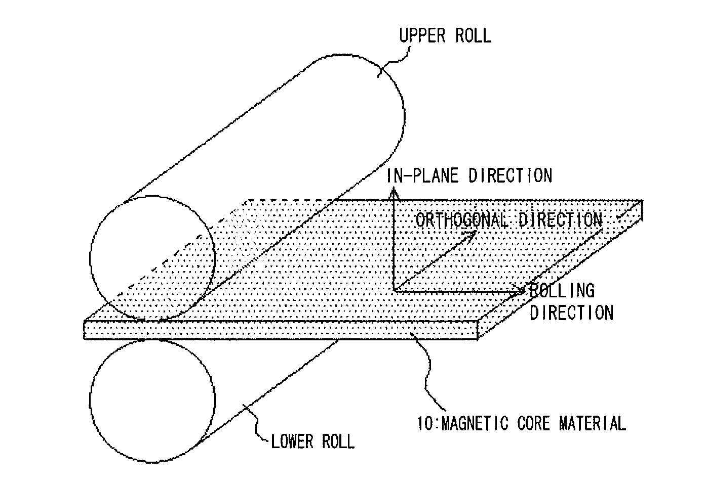
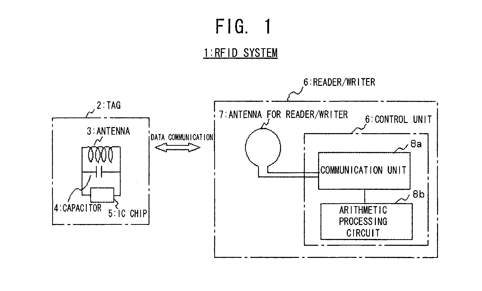
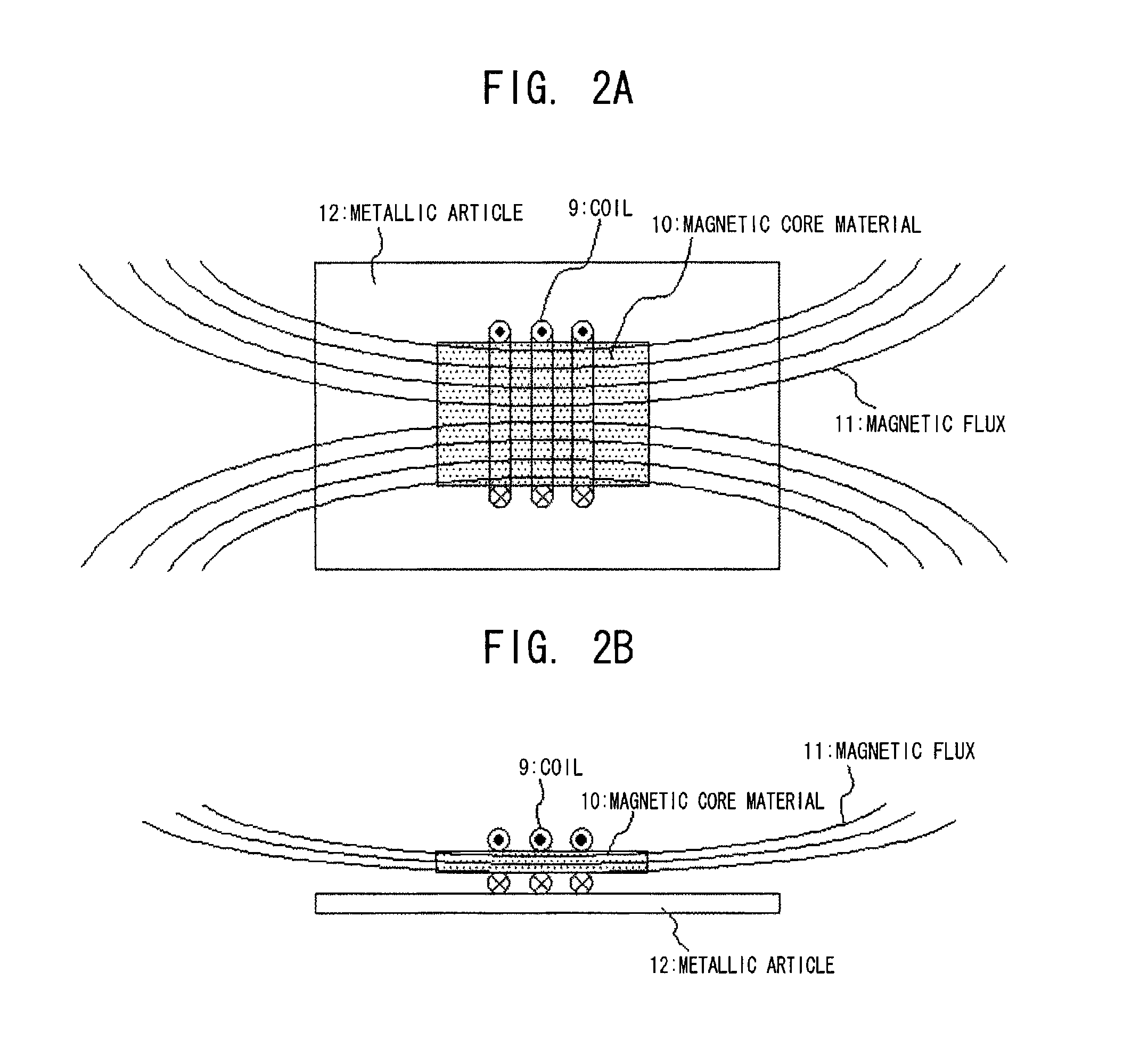
[0060] In order to describe the above-mentioned embodiment of the invention in more detail, examples in which the magnetic core material of the invention is applied to an antenna for an RFID tag or reader / writer with reference to FIGS. 1 to 9. FIG. 1 is a view schematically showing the general configuration of an RFID system, and FIG. 2 is a view schematically showing the configuration of an antenna of this working example. Further, FIG. 3 is a view schematically showing a manufacturing method and a sectional structure of a magnetic core material of this working example, and FIG. 4 is a view showing the configuration of a conventional antenna. Further, FIGS. 5 to 9 are views showing variations of the configuration of the antenna of this working example. In addition, although a case where the magnetic core material of the invention is applied to an antenna for tags is shown below, the invention is not limited to the following working examples, and the magnetic core material of the in...


PUM

PropertyMeasurementUnit
diameteraaaaaaaaaa
frequencyaaaaaaaaaa
frequencyaaaaaaaaaa

Abstract

A soft magnetic metal powder having a predetermined particle size (about 1 μm) or less is kneaded with plastic or rubber in a volume ratio of about 10% to 50%, and preferably, in a content of 10% to 40%, and the kneaded composite is subjected to working which extends a composite material in one direction, such as extruding, rolling, rolling after extruding, drawing after extruding, or rolling after injection. As a result, the magnetic permeability can be enhanced, the direction dependency can be given to magnetic permeability, the dimensional accuracy can be improved, and the magnetic core material can be made hard to be damaged.

Description

CROSS REFERENCE TO PRIOR APPLICATION [0001] This is a U.S. national phase application under 35 U.S.C. §371 of International Application No. PCT / JP2005 / 001997 filed Feb. 10, 2005 and claims the benefit of Japanese Application No. 2004-036065, filed Feb. 13, 2004. The International Application was published in Japanese on Aug. 25, 2005 as International Publication No. WO 2005 / 078746 under PCT Article 21(2).TECHNICAL FIELD [0002] The present invention relates to a magnetic core material, and particularly, to a high-frequency magnetic core material which is suitable to be used for an antenna of an RFID tag or an RFID reader / writer which operates in the range of a VHF band to a UHF band, its manufacturing method, and an antenna including the magnetic core material. BACKGROUND ART [0003] In recent years, an RFID system which communicates data between a tag including an IC chip, and a reader, a writer, or a reader / writer (hereinafter generically referred to as “reader / writer”) has come int...

Claims


Application Information

Patent Timeline
Patent Type & Authority Applications(United States)
IPC IPC(8): B32B15/00B42D15/10G06K19/07G06K19/077H01F1/22H01F1/26H01F1/44H01F41/02H01Q7/08
CPCG06K19/07771H01F1/26Y10T428/32H01Q7/08H01F41/0246
Inventor ENDO, TAKANORI
Owner MITSUBISHI MATERIALS CORP
Why Eureka
Try Eureka