In-line cyclone separator

a cyclone separator and separator technology, applied in the direction of vortex flow apparatus, liquid degasification, separation process, etc., can solve the problems of deteriorating the separation characteristics of the separator, relatively high pressure drop, and high pressure drop across the gas-outlet, so as to improve the separation efficiency of the separator, improve the separation characteristics, and improve the separation efficiency

Inactive Publication Date: 2008-01-10
FMC TECH CV
View PDF12 Cites 54 Cited by
  • Summary
  • Abstract
  • Description
  • Claims
  • Application Information

AI Technical Summary

Benefits of technology

[0020] By arranging the elongate openings in an oblique manner with respect to the axial direction (z-direction in the drawings) of the outlet element the circumferential movement (rotation) of the rotating mixture can be followed more easily, resulting in a more natural way of guiding the gas through the openings, with less change of the directions of the gas, and discharging the gas from the gas-outlet. A further effect is that the rotating movement of the mixture remains more stable for a longer axial distance, as a result of which the liquid carry-over in the gas-outlet is minimized. Also the pressure drop across the gas-outlet is only a fraction of the pressure drop in the conventional degasser outlet.
[0037] According to another aspect of the present invention, a method is provided for separating a mixture containing solid particles, liquid and / or gas into a heavy fraction and a light fraction. The method includes feeding the mixture through an inlet of a cyclone separator into a flow space of the cyclone separator and guiding the mixture along one or more swirl-elements of the cyclone separator for causing the mixture to rotate so as to fling the heavy fraction into a outer region adjacent the inner surface of the outer casing and so as to keep the light fraction in a central region. The method further includes guiding the heavy fraction in the outer region through an outer passage of the cyclone separator, discharging the heavy fraction from a first outlet of the cyclone separator and guiding the light fraction in a core region of the cyclone separator through an opening in an outlet element of the cyclone separator and discharging the light fraction from a second outlet of the cyclone separator.

Problems solved by technology

One of the disadvantages of the degasser is that this type of separator—can be operated in case of a liquid continuous flow, i.e. a mixture wherein the main constituent is the liquid and wherein only gas bubbles exist when it is a two phase mixture.
A further disadvantage of the known degasser is at above a certain gas fraction the pressure drop across the gas-outlet becomes very high.
This means that gas removal can lead to a collapse of the above mentioned gas core / liquid film which will create unstable behavior and will deteriorate the separation characteristics of the separator.
A further drawback of the known degasser is that gas removal implies twice a directional change of the gas causing a relatively high pressure drop.
For high gas loads with a volumetric gas fraction above 30% this may result in relatively large pressure drops and limited gas removal capacity.
A further drawback is that the gas-outlet pipe forms a disturbance in the flow space of the separator, which may result in controllability problems due to the sudden removal of the driving phase (i.e. the gas).
The abrupt removal of the gas may moreover lead to a collapsing liquid film, which also has a negative effect on the separation characteristics, for example the separation efficiency, of the deliquidiser.

Method used


Image

  • In-line cyclone separator
  • In-line cyclone separator
  • In-line cyclone separator

Examples


Embodiment Construction

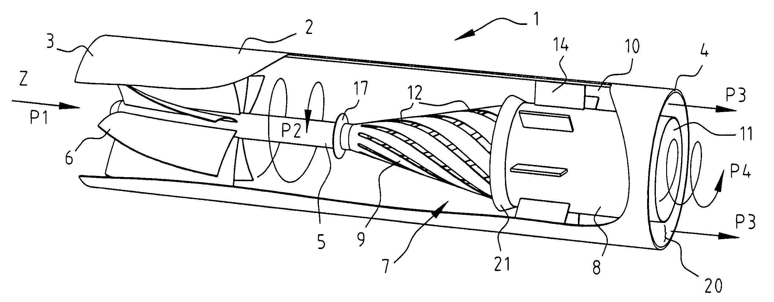
[0044] The embodiments of the separators according to the present invention shown in the drawings are especially intended for separation of a gas phase (gas phase vapor) from a liquid phase (water / oil), for example in a pipeline leading to an oil platform. However, as indicated earlier, the separators can be used separating any mixture of one or more liquids, one or more gasses and / or one of more different types of solid particles.

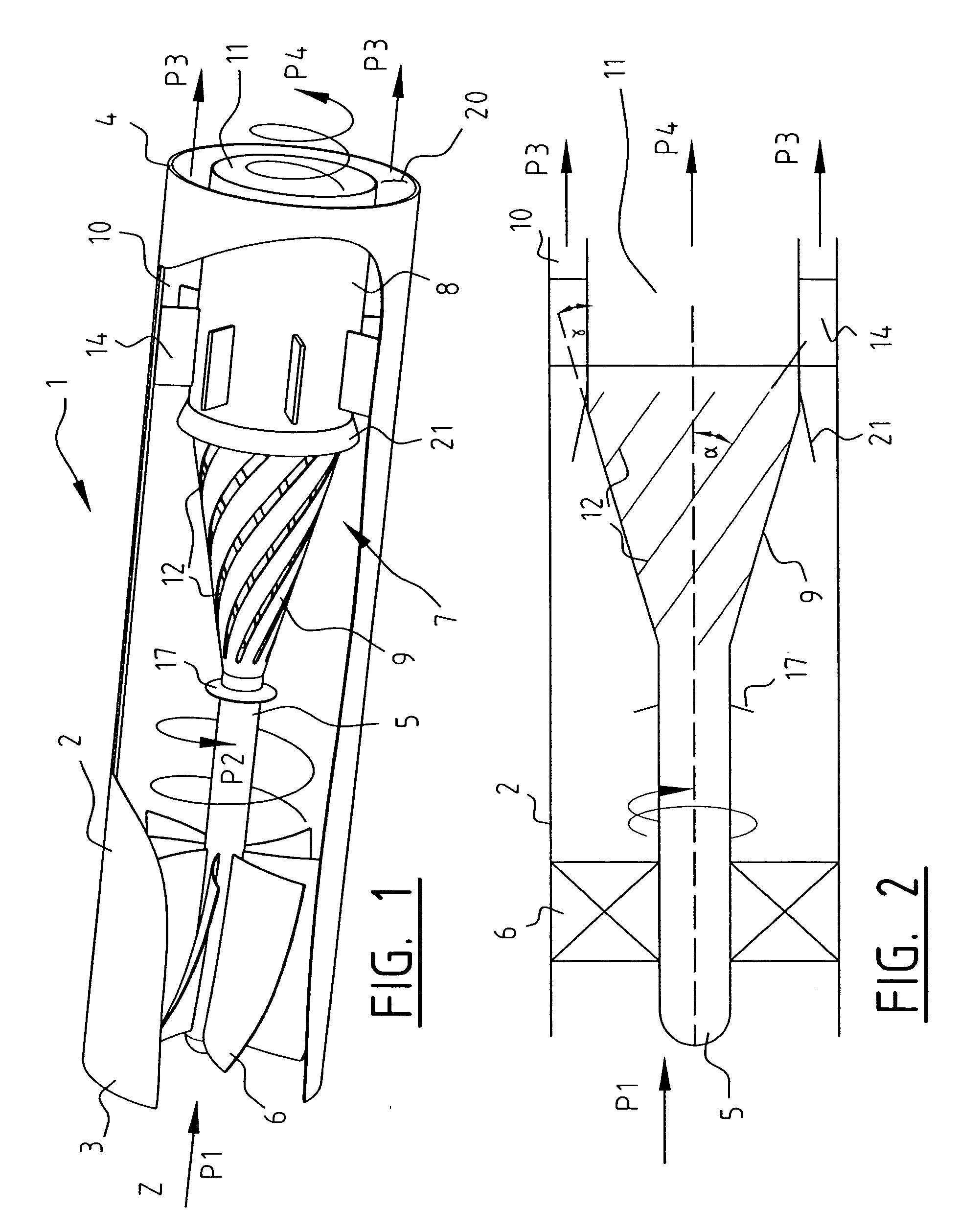
[0045]FIG. 1 shows a separator 1, including a tube 2 which at its proximal end is provided with an inlet 3 for connecting to the supply part of a pipeline (not shown) and which at its distal end is provided with an outlet 4 for connecting to a further part (not shown) of the pipeline. In the flow space defined by the interior of the tube 2 a central flow body5 is arranged, extending in the axial direction (or Z-direction, as shown in FIG. 1).

[0046] Between the inner surface of the tube 2 and the outer surface of the flow body 5 are arranged a number of c...


PUM

PropertyMeasurementUnit
angleaaaaaaaaaa
angleaaaaaaaaaa
angleaaaaaaaaaa

Abstract

A cyclone separator for separating a mixture containing solid particles, liquid and / or gas into a heavy fraction and a light fraction. the cyclone separator including an outer casing defining a flow space through which, the mixture is to flow and having an inlet for an incoming mixture. A first outlet for the separated light fraction and a second outlet for the separated heavy fraction and a flow body arranged in the outer casing and along which the mixture to be separated is carried. at least one swirl element arranged in the outer casing and between the flow body and the outer casing for setting the mixture into a rotating movement for the purpose of separating the mixture into the heavy and light fractions. an outlet element having a central, axially extending inner passage connected to the first outlet for discharge of the light fraction and an outer surface which, together with an inner surface of the outer casing, defines an outer passage connected to the second outlet for discharge of the heavy fraction, the outlet element being provided with one or more elongated openings through which the light fraction can enter the inner passage, the one or more elongate openings extending obliquely with respect to an axial direction of the outlet element.

Description

RELATED APPLICATIONS [0001] Applicants claim, under 35 U.S.C. §119, the benefit of priority of the filing date of May 26, 2004 of a Dutch patent application, copy attached, Serial Number 1026268, filed on the aforementioned date, the entire contents of which is incorporated herein by reference. BACKGROUND OF THE INVENTION [0002] 1. Field of the Invention [0003] The present invention relates to a cyclone separator for separating a mixture containing solid particles, liquid and / or gas into a light fraction and a heavy fraction. The present invention also relates to a method of separating the mixture in the separator. The present invention also relates to a pipe for transporting said mixture, the pipe being provided with at least one of the cyclone separators. [0004] 2. Discussion of Related Art [0005] Numerous devices are known for separating incoming flows of various liquids (far example oil and water), gas and solid particles (dust particles), liquid and gas (for example oil and nat...

Claims


Application Information

Patent Timeline
Patent Type & Authority Applications(United States)
IPC IPC(8): B01D45/14B01D17/02B01D19/00B01D21/26B01D45/12B04C3/06
CPCB01D17/0217B01D19/0057B01D21/265B04C3/06B04C2003/006B01D45/12Y10T137/794
Inventor LARNHOLM, PER-REIDARSCHOOK, ROBERT
Owner FMC TECH CV
Why Eureka
Try Eureka