Stress isolated pressure sensing die

a pressure sensing die and stress isolation technology, applied in the direction of fluid pressure measurement using elastically deformable gauges, measuring devices, instruments, etc., can solve the problem of thermal mismatches appearing at determinate temperatures

Active Publication Date: 2008-01-10
AUXITROL
View PDF8 Cites 38 Cited by
  • Summary
  • Abstract
  • Description
  • Claims
  • Application Information

AI Technical Summary

Benefits of technology

[0028] The said sensing structure is thus prevented from deforming the sensing diaphragm and locked-in residual null offset in the sensing elements.
[0029] The short and long

Problems solved by technology

Indeed thermal mismatch may appear at determinate temperatures if the sensing

Method used


Image

  • Stress isolated pressure sensing die
  • Stress isolated pressure sensing die
  • Stress isolated pressure sensing die

Examples


Embodiment Construction

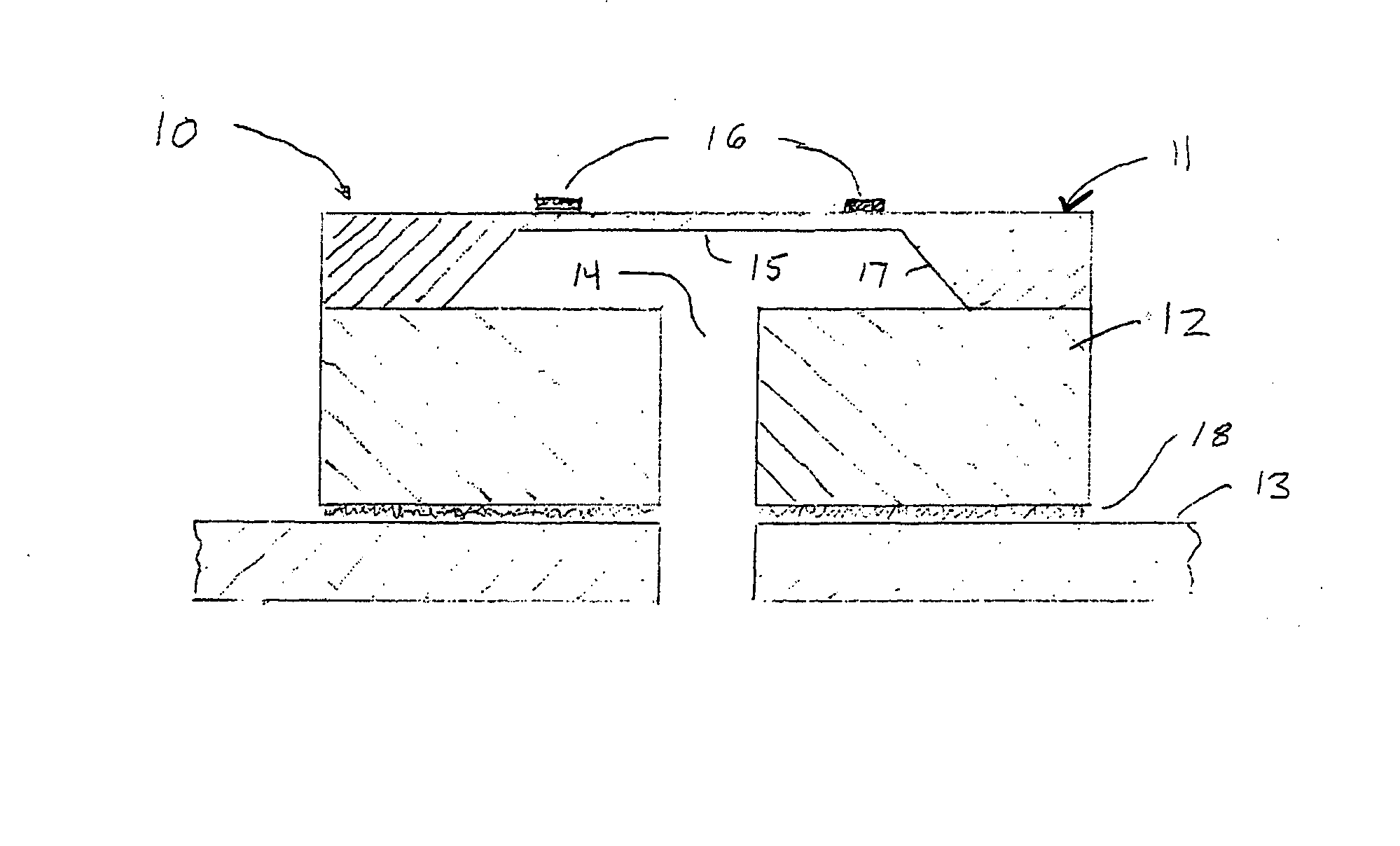
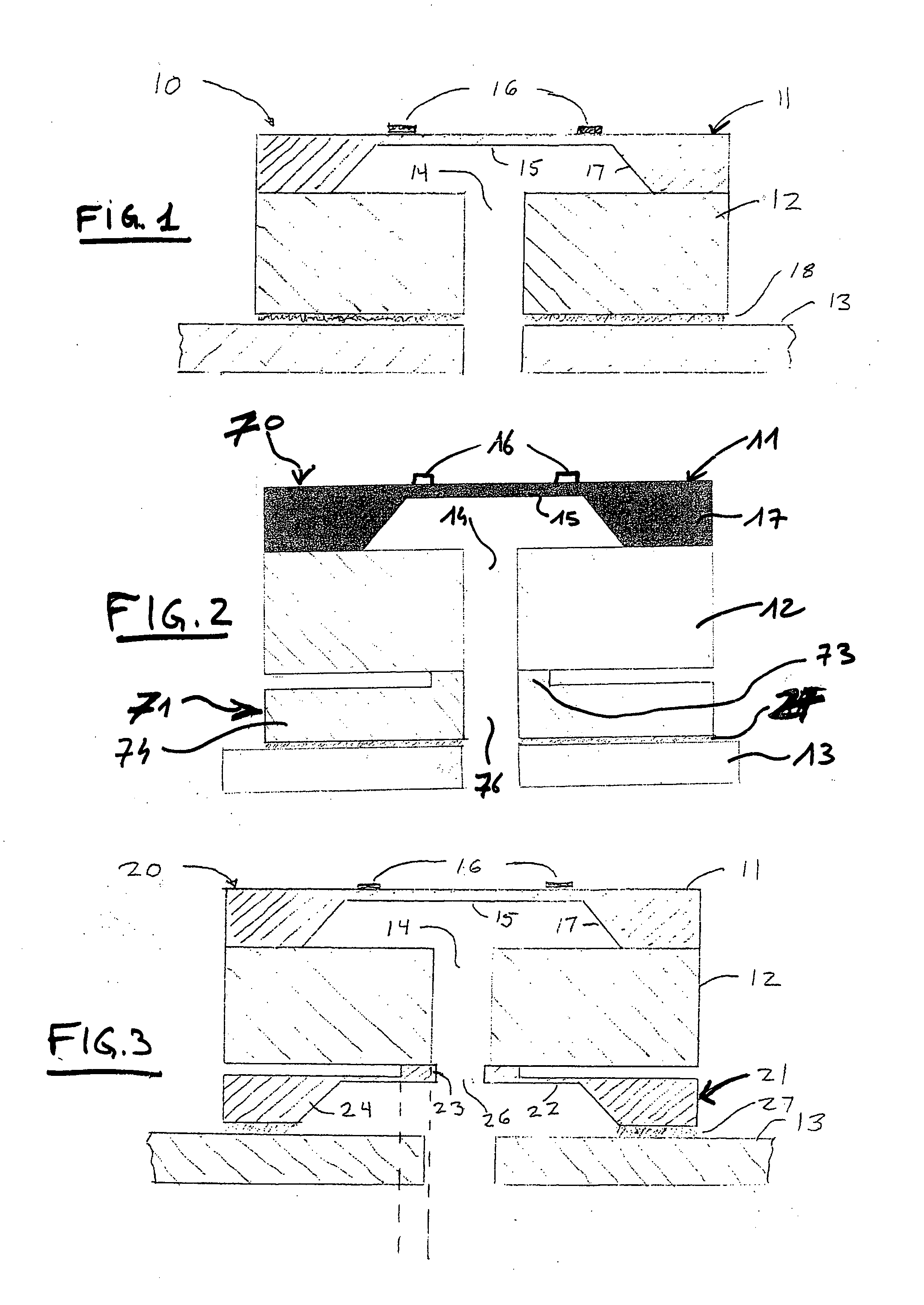
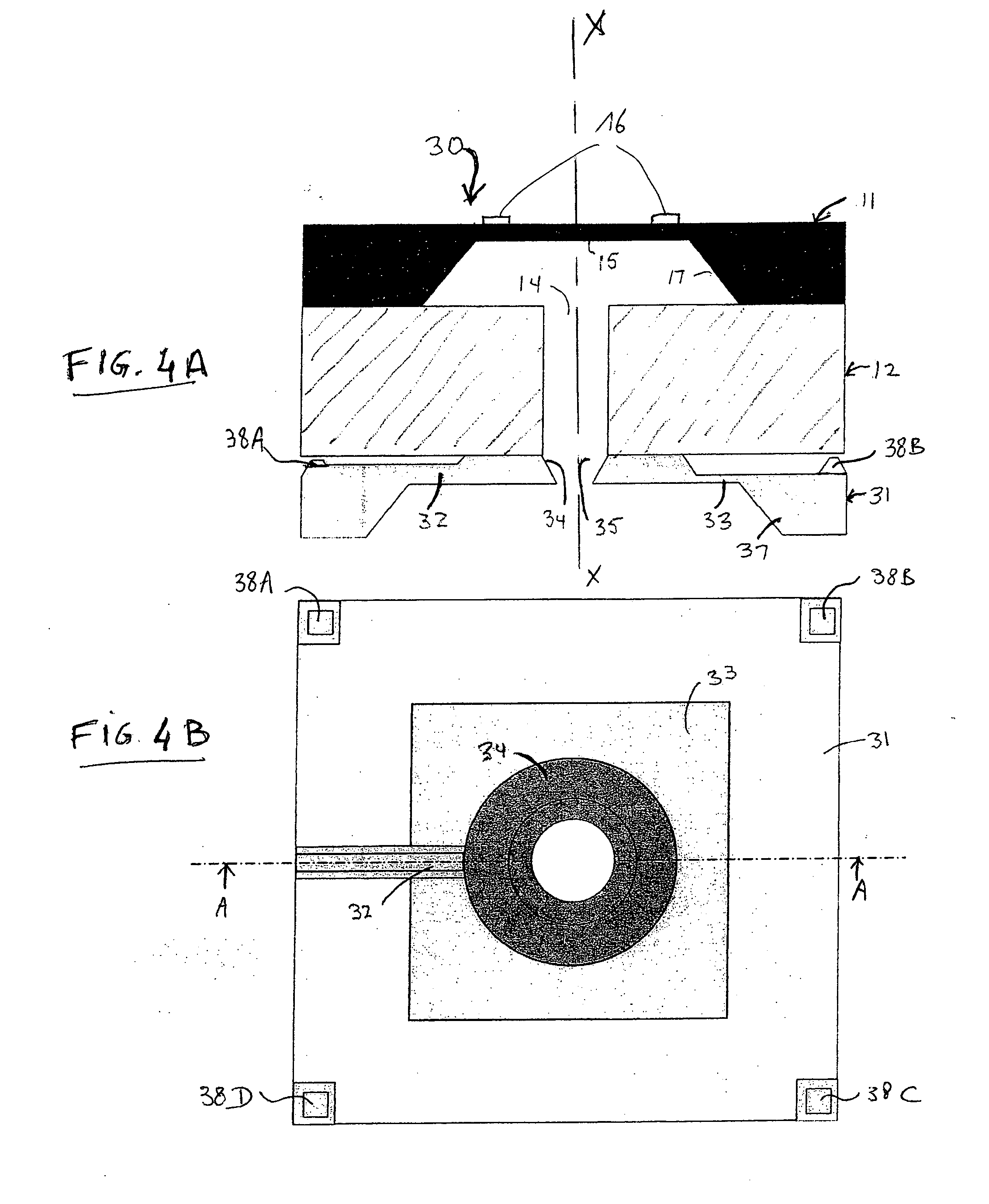
[0075]FIGS. 2, 3A, 4A, 4C and 5A illustrate cross-sectional views of different triple stack sensor dies 20 according to invention, comprising a pressure sensing capsule 11-12, employing a linking structure 71 (FIG. 2), 21 (FIG. 3A), 31(FIG. 4A), 61(FIG. 4C), 31A (FIG. 5A), mounted on a base 13.

[0076] The sensing capsule 11-12 comprising a diaphragm structure 11 on a pedestal 12.

[0077] The diaphragm structure 11 comprises an outer frame 17 and a deflectable sensing diaphragm 15 suspended over the outer frame 17. The sensing diaphragm 15 is arranged for deflecting under a pressure applied thereon, the deflection being representative of the applied pressure.

[0078] The deflectable sensing diaphragm 15 is typically manufactured by etching away substance from a portion of an initial wafer, e.g. according to a square or round pattern, or by other well-known techniques.

[0079] Sensing elements 16, like Piezoresistors or strain gauges, are then deposited or formed, e.g. by diffusion or im...


PUM


Abstract

The invention relates to a pressure sensing die to be mounted on a base, comprising: a sensing structure comprising: a diaphragm structure with a deflectable sensing diaphragm whose deflection is representative of the pressure and sensing elements for detecting the deflection of the sensing diaphragm, a pedestal supporting the diaphragm structure, a linking structure for isolating at least some of the stresses caused by the mounting of the sensing die on the base from said deflectable sensing diaphragm, the linking structure being linked on one side to a bottom surface of the pedestal and to be linked, on an opposite side, to a top surface of the base, wherein the linking structure comprises at least one linking element extending between the base and the pedestal and having a mean cross-section smaller than the said bottom surface and top surface so as to constitute a small link between the base and the pedestal. The invention further relates to a method of manufacturing such a sensing die.

Description

FIELD OF THE INVENTION [0001] The present invention relates to pressure sensor assemblies, comprising: [0002] a sensing die including a deflectable sensing diaphragm whose deflection is representative of the pressure and sensing elements for detecting the deflection of the diaphragm; [0003] a base supporting the sensing die. [0004] Particularly, the invention relates to such dual stack sensor MEMS assemblies, wherein the sensing die further comprises a Pyrex® pedestal supporting the sensing diaphragm, mounted on bases such as metal headers or substrates made of ceramic or plastic. BACKGROUND OF THE INVENTION [0005] Referring to FIG. 1, most known pressure sensing MEMS sensing dies are composed of dual stack dies manufactured by anodic bonding two wafers: [0006] a silicon wafer 11: a silicon wafer bulk-machined to have at least one thin diaphragm 15 supported by a rigid outer frame 17. Strain gauges, or piezoresistors, 16 are placed on or in the diaphragm 15 in order to sense the str...

Claims


Application Information

Patent Timeline
IPC IPC(8): G01L7/08
CPCG01L19/146
Inventor BRIDA, SEBASTIANOBROSH, AMNON
Owner AUXITROL
Why Eureka
Try Eureka