Tappet assembly

a technology of taper and assembly, which is applied in the direction of valve drives, machines/engines, fuel injecting pumps, etc., can solve the problems of seizing and/or cracking of rollers, failure of one or more components of the assembly, and none of these assemblies have utilized a coating such as wcc on the outer surface of the rollers

Active Publication Date: 2008-01-10
CATERPILLAR INC
View PDF19 Cites 27 Cited by
  • Summary
  • Abstract
  • Description
  • Claims
  • Application Information

AI Technical Summary

Problems solved by technology

For heavy duty applications, the loads on such tappet assemblies may be significant, which can cause failure of one or more components of the assembly if the assembly is not constructed robustly enough.
Areas of stress concentrations can act as the weakest link in an otherwise robust assembly, leading to seizing and / or cracking of rollers.
In addition, poor frictional properties of mating components may also lead to failure, particularly during engine start-up when lubrication oil may not have been circulated yet.
However, none of these assemblies have utilized a coating such as WCC on the outer surface of the roller.
While the device disclosed in the '313 patent may disclose a configuration designed to reduce stresses between the pin and roller, the interface between the roller and camshaft follower lifting surface is not configured such that a footprint of contact pressure from the camshaft follower lifting surface, at maximum operational loading conditions of the machine, is spread substantially the full width of the outer surface of the roller.
Concentration of high loads in such a narrow contact patch results in high stresses that may render the roller susceptible to failure.

Method used


Image

  • Tappet assembly
  • Tappet assembly
  • Tappet assembly

Examples


Embodiment Construction

[0020] Reference will now be made in detail to the drawings. Wherever possible, the same reference numbers will be used throughout the drawings to refer to the same or like parts.

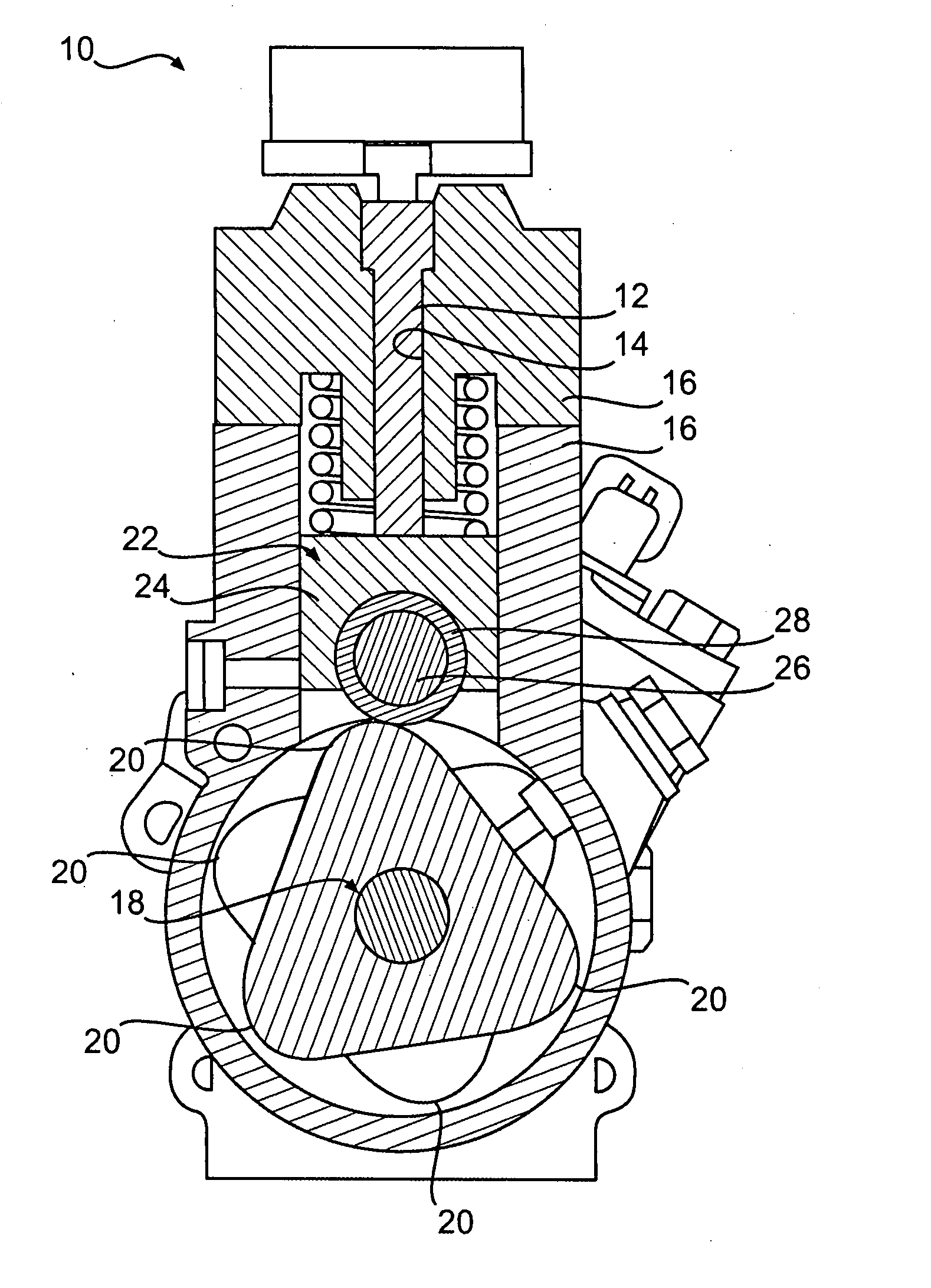
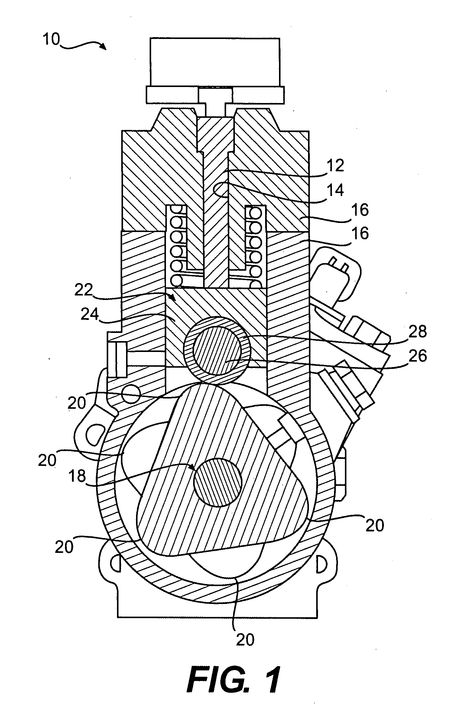
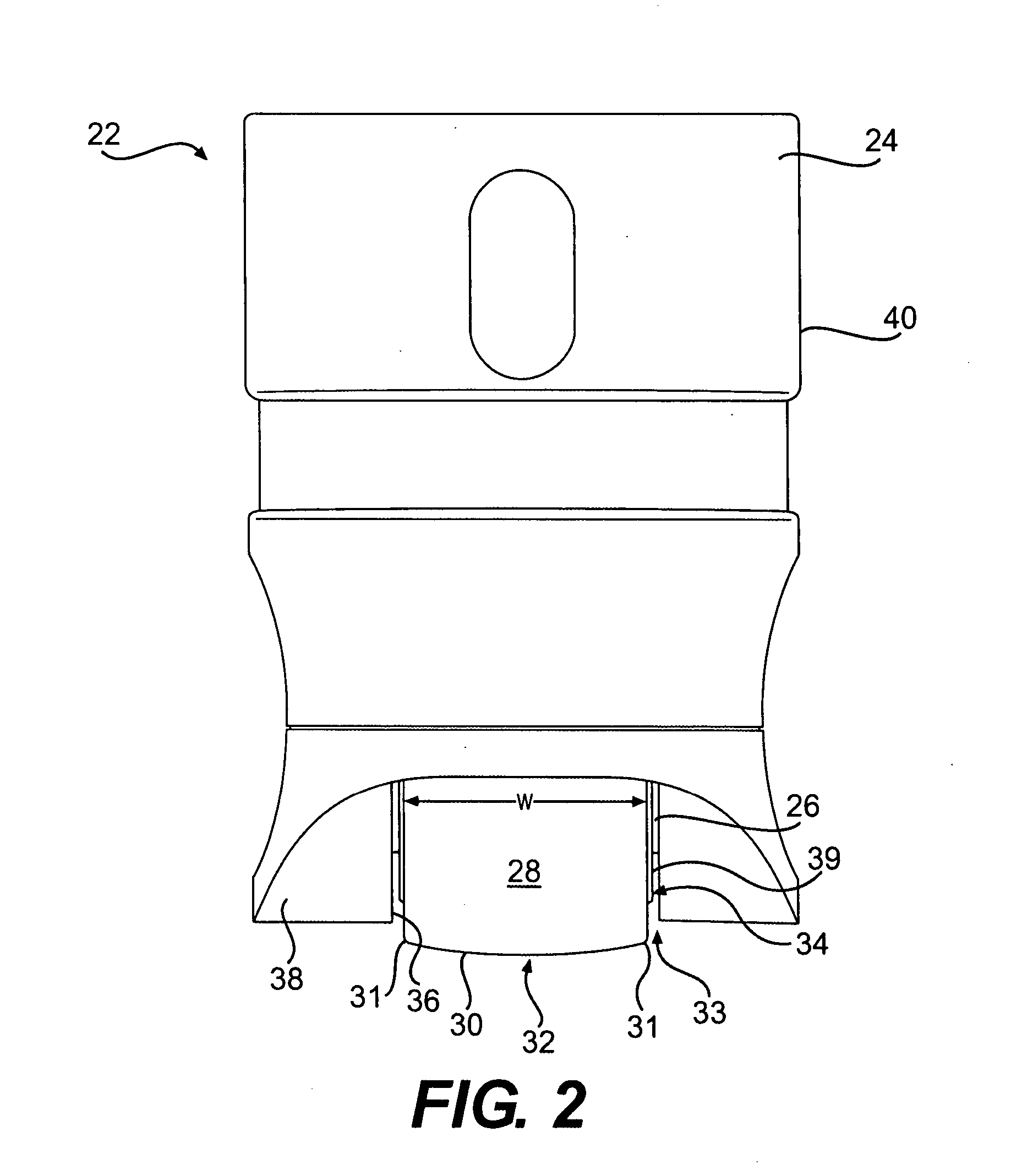
[0021]FIG. 1 shows an exemplary common rail fuel pump 10, which may include a plunger 12 configured to slide within a cylindrical bore 14 of a housing 16 in order to pressurize fuel in the common rail system. Plunger 12 may be driven by a cam 18 having at least one cam lobe 20 configured to drive a tappet assembly 22 operatively connected to plunger 12. Tappet assembly 22 may include a tappet body 24 and a cylindrical pin 26 fixedly mounted in tappet body 24. Tappet assembly 22 may also include a substantially cylindrical roller 28 mounted about pin 26 and configured to provide rolling contact with cam lobe 20. Although shown in a common rail fuel pump application, tappet assembly 22 may be used for any application of a tappet, as discussed in greater detail below.

[0022] In some embodiments, pin 26 may be...


PUM


Abstract

In one aspect, the present disclosure is directed to a tappet assembly for a machine. The assembly may include a tappet body, a pin fixedly mounted in the tappet body, and a substantially cylindrical roller mounted about the pin. The roller may have a substantially cylindrical outer surface with a circumferential dimension and a width dimension, the width dimension being defined by two lateral edges. The roller may be configured to provide rolling contact between the outer surface of the roller and a cam lobe. The outer surface of the roller may be crowned such that at maximum operational loading conditions of the machine a footprint of contact pressure from the cam lobe is spread substantially the full width of outer cylindrical surface of the roller.

Description

PRIORITY [0001] The present application claims the benefit of priority under 35 U.S.C. § 119(e) to U.S. provisional patent application No. 60 / 817,391, filed Jun. 30, 2006.TECHNICAL FIELD [0002] The present disclosure is directed to a tappet assembly and, more particularly, to a tappet assembly having features for reducing stress and friction. BACKGROUND [0003] Fuel systems for engines may include pumping devices configured to pressurize the fuel prior to injection into the combustion chambers of the engine. For example, in common rail fuel systems, a tappet assembly may be configured to drive a plunger and / or piston, which may be configured to pressurize the fuel. The tappet assembly may include a tappet having a pin attached to the tappet and a roller mounted about the pin, and configured to rotate around it. The roller may be configured to contact a cam lobe, which drives the tappet up and down. [0004] For heavy duty applications, the loads on such tappet assemblies may be signifi...

Claims


Application Information

Patent Timeline
Patent Type & Authority Applications(United States)
IPC IPC(8): F01L1/14
CPCF01L1/08F01L1/146F01L2105/02F02M59/102F02M59/445F01L1/16F02M2200/02F02M2200/9038F02M2200/9053F02M2200/9076F02M59/48F02M63/0001F01L2305/02
Inventor BARTLEY, BRADLEY E.STOCKNER, ALAN R.MACK, DAVID C.
Owner CATERPILLAR INC
Why Eureka
Try Eureka