Electrical circuit breaker

a circuit breaker and circuit technology, applied in the direction of explosion switch closing, high-tension/heavy-duty switch, etc., can solve the problems of high cost, high installation cost, and still flowing circuit current, so as to reduce the ability to withstand short-circuits, high protection level for persons, and fast and simple

Inactive Publication Date: 2008-01-10
KLOCKNER-MOELLER GMBH
View PDF5 Cites 19 Cited by
  • Summary
  • Abstract
  • Description
  • Claims
  • Application Information

AI Technical Summary

Benefits of technology

[0027] As long as the short-circuit is still present in the short circuiter, it should not be possible to switch the circuit breaker back on. Switching the circuit breaker back on should only be possible once the short-circuit has been eliminated, which can be done by exchanging the short circuiter with a properly functioning short circuiter or by replacing the non-functioning parts or else by not replacing the short circuiter. This achieves a high level of protection for persons and equipment.
[0028] The circuit breaker can be used in practically all conventional switchgear cabinets of electrical installations. The installation and start-up of the short circuiter in the circuit breaker can be carried out quickly and simply. The result is a compact unit. It does not require additional space. For these reasons, the circuit breaker can replace existing switching systems within the scope of a retrofitting procedure.
[0029] The conductors and the conductor bars of the circuit brea

Problems solved by technology

After the short circuiter has been tripped, a short-circuit current is still flowing that is interrupted by the serially connected incoming circuit breaker (after its turn-off time), as a result of which the defective electrical install

Method used


Image

  • Electrical circuit breaker
  • Electrical circuit breaker
  • Electrical circuit breaker

Examples


Embodiment Construction

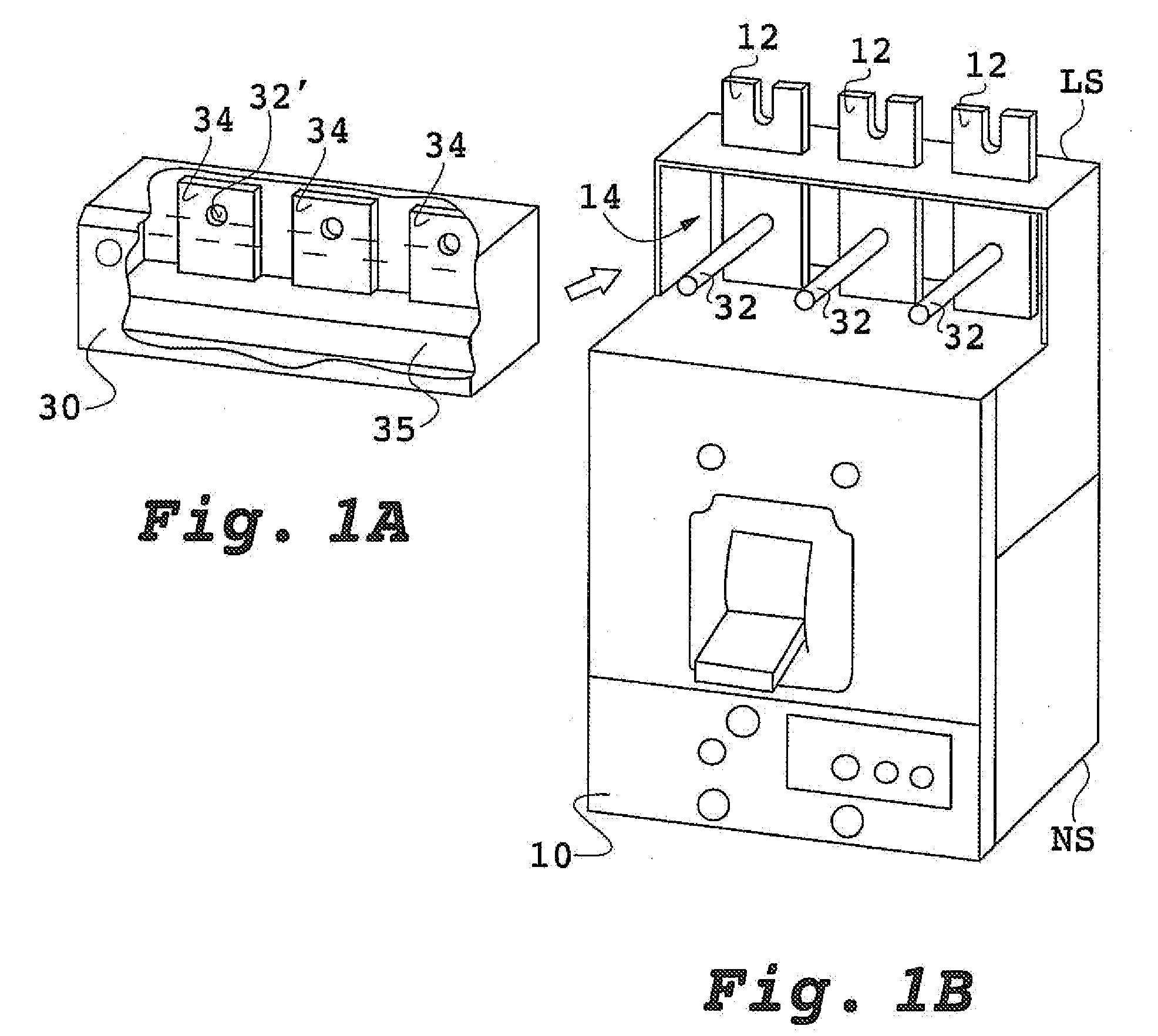
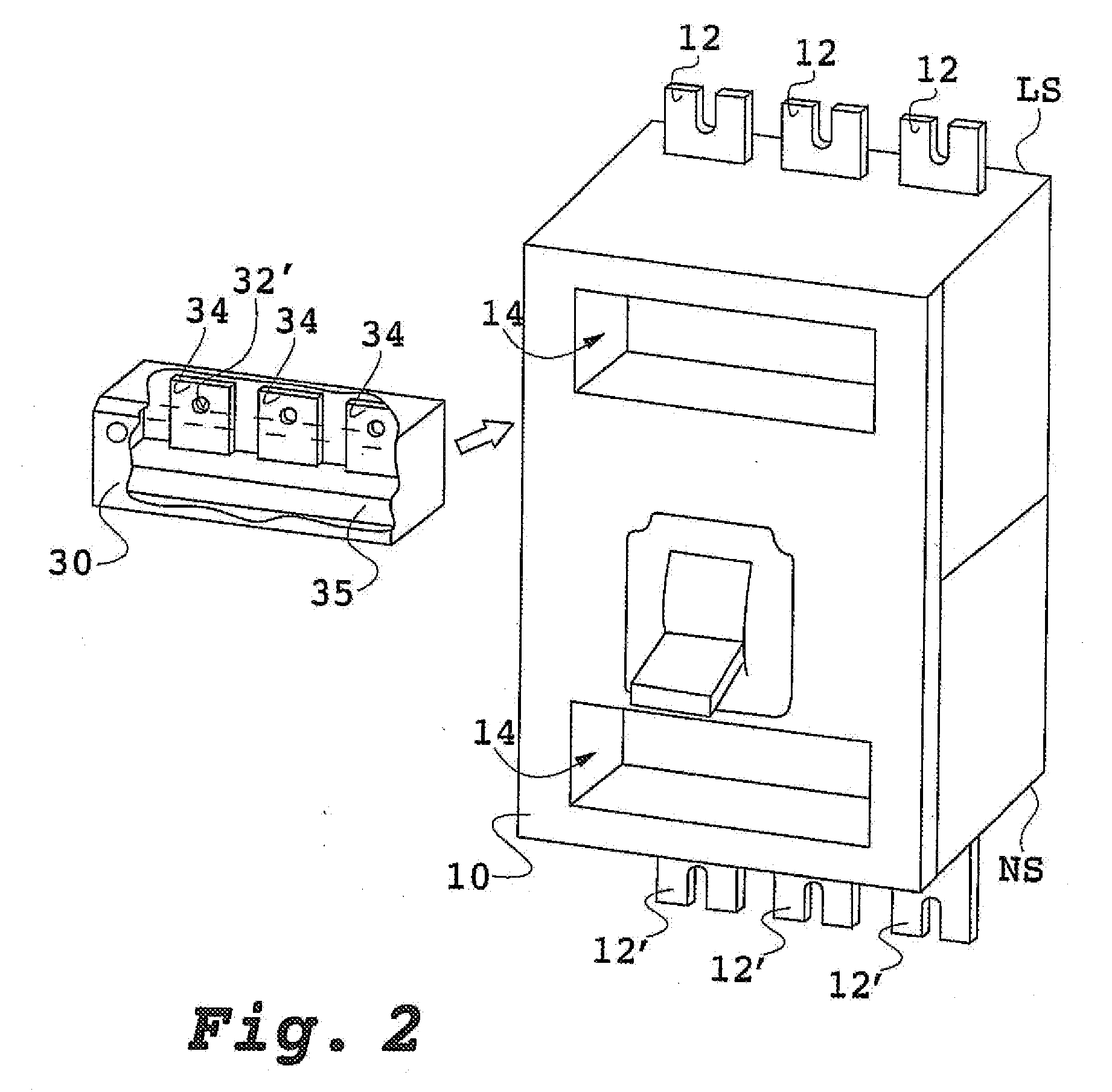
[0034] The depictions in the figures show a circuit breaker configured as a power breaker 10 that is installed in a three-phase (L1, L2, L3) electrical power system upstream from an electrical consumer 40. The circuit breaker has a detection unit (short-circuit actuator) and an overload release that can be configured as a bimetal release. Overload releases operate with a time delay when a high, pre-adjustable current intensity occurs and cause the contacts of the circuit breaker to open via the breaker latch 16. The provided detection unit 20 is present in the form of an electronic unit that is actuated by the current-detection means 21. Current transformers, for instance, Hall sensors, can be provided as the current-detection means.

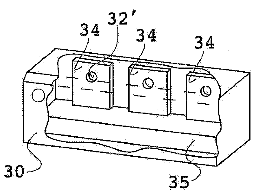
[0035] The circuit breaker is contained in such a way that a short circuiter can be connected to at least one fastening site.

[0036] For this purpose—according to FIG. 1B—on the load side LS of the circuit breaker, the conductor bars 12 of each phase L1...


PUM


Abstract

A circuit breaker for multi-phase power includes an opening-closing apparatus configured to open and close each phase of the multiphase power, a detection unit configured to detect a fault current in at least one phase of an electrical installation, a plurality of connecting bars disposed on a load side of the circuit breaker, and a fastening device disposed on the connecting bars and configured to detachably fasten a short circuiter to the connecting bars, the short circuiter configured to create a short circuit between the connecting bars when a fault is detected by the detection unit. The option proposed according to the invention of installing a short circuiter means that the circuit breaker is fully operational, either with or without the installation of a short circuiter.

Description

[0001] Priority is claimed to German Patent Application No. DE 10 2006 030 672.4, filed on Jul. 4, 2006, the entire disclosure of which is incorporated by reference herein. [0002] The present invention relates to an electric circuit breaker, especially to a power breaker for low voltage. BACKGROUND [0003] When a fault current occurs, especially an overcurrent, or when a short-circuit or an arcing fault occurs, the current-breaking capacity and turn-off time of a power breaker are dependent on various parameters. The turn-off process is made up of the tripping time, the inherent delay and the turn-off time. The tripping time is the time from the occurrence of the variable that causes the tripping until the initiation of the tripping process, for instance, the release of a breaker latch. This is followed by the inherent delay of the circuit breaker, which is determined by the dynamic processes of the contacts of the circuit breaker as they move and open. A turn-off time of about 30 to...

Claims


Application Information

Patent Timeline
IPC IPC(8): H01H9/30
CPCH01H39/004H01H79/00H01H71/08H01H71/0228H02H1/0015
Inventor BOEDER, FRANZSCHUMACHER, ANDREASFRIEDRICH, VOLKER
Owner KLOCKNER-MOELLER GMBH
Why Eureka
Try Eureka