Multi-anode type photomultiplier tube and radiation detector

a multi-anode type, radiation detector technology, applied in the direction of instruments, tubes with screens, image-conversion/image-amplification tubes, etc., can solve the problems of insufficient strength of the side tubes, inability to guide the scintillation light uniformly, etc., to increase the size of the photocathode, small cross-section, and large cross-section

Active Publication Date: 2008-01-10
HAMAMATSU PHOTONICS KK
View PDF12 Cites 7 Cited by
  • Summary
  • Abstract
  • Description
  • Claims
  • Application Information

AI Technical Summary

Benefits of technology

[0008] It is conceivable to modify the quadrangular-prism-shaped glass side tube described in Japanese unexamined patent application publication No. 11-250853 into a structure that includes a quadrangular-prism-shaped hollow tube head having a relatively large cross-section and a quadrangular-prism-shaped hollow tube main body having a relatively small cross-section, similar to the side tube described in Japanese unexamined patent application publication No. 03-173056. Because the cross-section of the tube head is large, it is possible to increase the size of the photocathode that is located on the faceplate at its area inside the side tube.
[0010] When the quadrangular-prism-shaped hollow side tube is made of glass, the side tube will be curved or rounded at its four corners. This reduces the amount of the area on the faceplate that falls inside the corners of the side tube.
[0012] An object of the present invention is therefore to solve the above-described problems and to provide a multi-anode type photomultiplier tube, which ensures that light effectively enters a photocathode and which has a high mechanical strength.
[0013] Another object of the present invention is to provide a radiation detector that includes the multi-anode type photomultiplier tube and that can detect scintillation light from all the scintillators in the scintillator matrix substantially uniformly.

Problems solved by technology

However, if the length of the tube head along the tube axial direction is longer than the length of the tube main body along the tube axial direction as disclosed in Japanese unexamined patent application publication No. 03-173056, the overall strength of the side tube will become insufficiently low.
Consequently, it is impossible to guide the scintillation light uniformly from all the scintillators in the scintillator matrix onto the photocathode.

Method used


Image

  • Multi-anode type photomultiplier tube and radiation detector
  • Multi-anode type photomultiplier tube and radiation detector
  • Multi-anode type photomultiplier tube and radiation detector

Examples


second embodiment

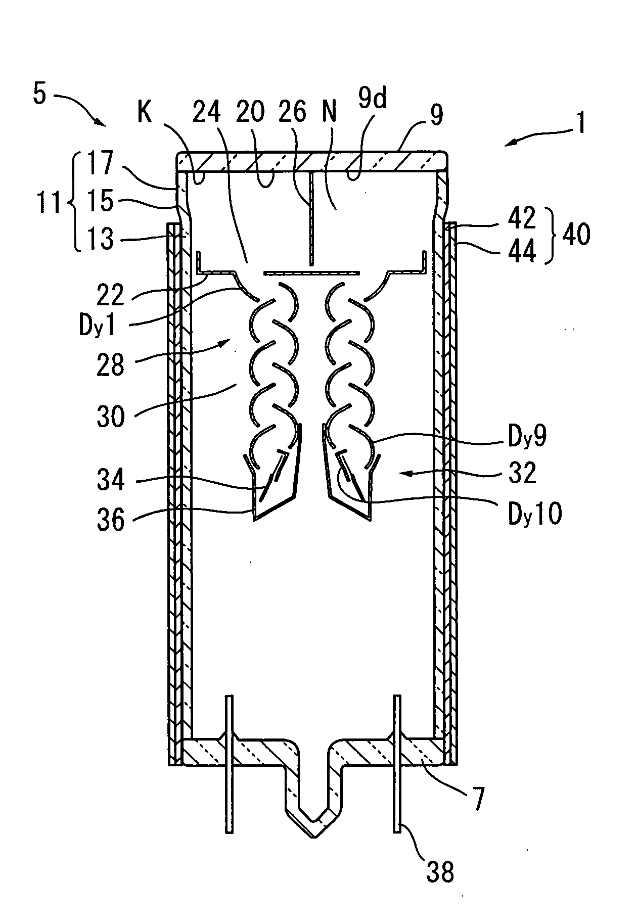
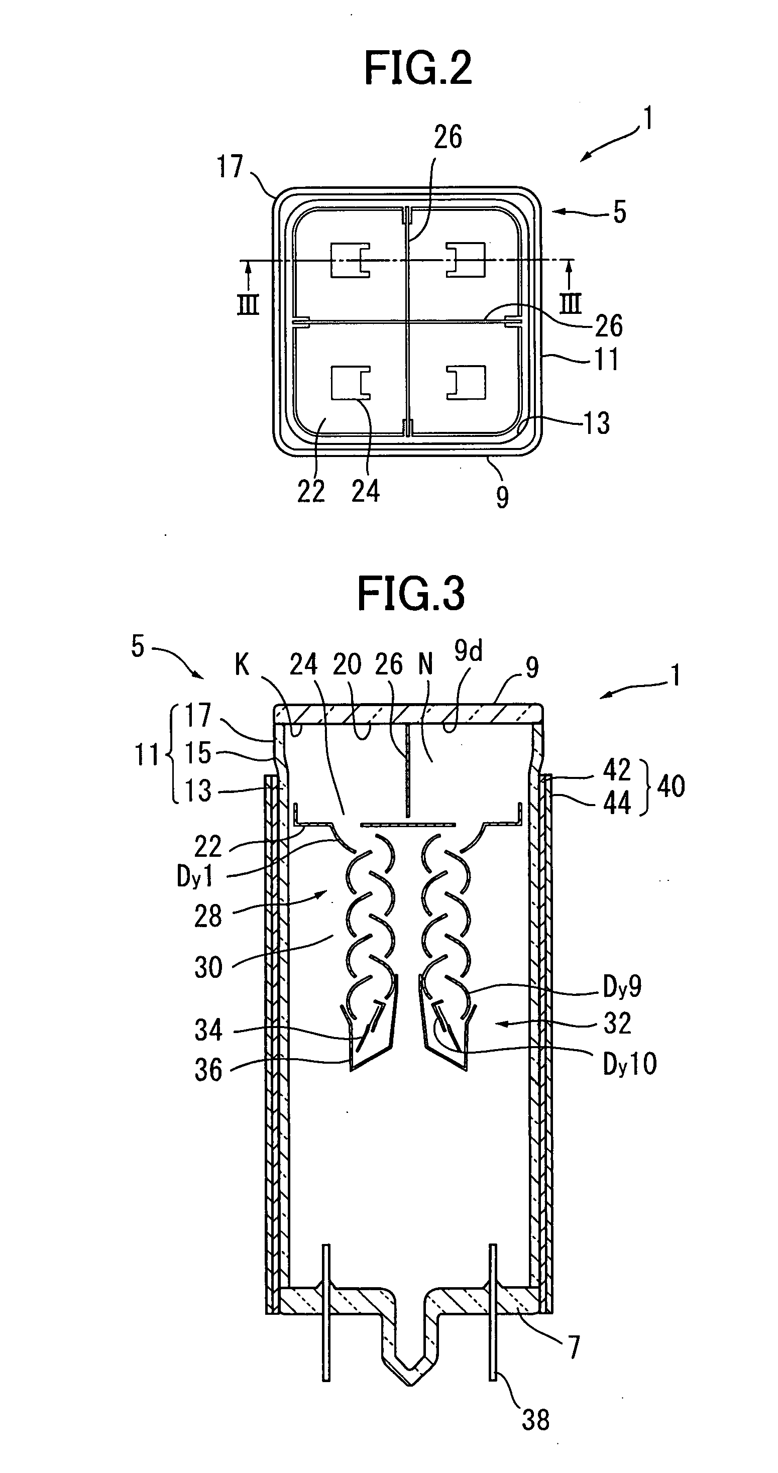
[0100] A multi-anode type photomultiplier tube and a radiation detector according to a second embodiment of the present invention will be described below with reference to FIGS. 2-6, 8, and 12.

[0101] The multi-anode type photomultiplier tube of the second embodiment (which will be referred to as “multi-anode type photomultiplier tube 1′,” hereinafter) has a tube head (which will be referred to as “tube head 17′,” hereinafter), whose cross-section is different from that of the tube head 17 of the first embodiment. The tube head 17′ has a cross-section shown in FIG. 12.

[0102] Except for the tube head 17′, the multi-anode type photomultiplier tube 1′ has substantially the same configuration as that of the multi-anode type photomultiplier tube 1 shown in FIGS. 2 and 3. More specifically, the multi-anode type photomultiplier tube 1′ has a glass vessel (which will be referred to as “glass vessel 5′,” hereinafter). The glass vessel 5′ has: an external shape substantially the same as that...


PUM


Abstract

A side tube includes a tube head, a funnel-shaped connection neck, and a tube main body, which are arranged along a tube axis and which are integrated together into the side tube. The size of a cross section of the tube head perpendicular to the tube axis is larger than the size of a cross section of the tube main body perpendicular to the tube axis. The radius of curvature of rounded corners of the tube head is smaller than the radius of curvature of rounded corners of the tube main body. The length of the tube head along the tube axis is shorter than the length of the tube main body along the tube axis. One surface of a faceplate is connected to the tube head. A photocathode is formed on the surface of the faceplate in its area located inside the tube head.

Description

CROSS-REFERENCE TO RELATED APPLICATION [0001] This is a Continuation of application Ser. No. 10 / 770,539 filed Feb. 4, 2004, which also claims benefit of Provisional application No. 60 / 477,361 filed on Jun. 11, 2003. The entire disclosures of the prior applications are hereby incorporated by reference in their entirety.BACKGROUND OF THE INVENTION [0002] 1. Field of the Invention [0003] The present invention relates to a multi-anode type photomultiplier tube and a radiation detector that employs the multi-anode type photomultiplier tube. [0004] 2. Description of the Related Art Japanese unexamined patent application publication No. 05-93781 discloses a radiation detector 200 shown in FIG. 1. This radiation detector 200 includes a scintillator matrix 201 and a multi-anode type photomultiplier tube 203. [0005] The scintillator matrix 201 includes a plurality of scintillators 202 that are arranged in a two-dimensional matrix manner. The scintillator matrix 201 generates and emits scintil...

Claims


Application Information

Patent Timeline
Patent Type & Authority Applications(United States)
IPC IPC(8): H01J43/04G01T1/20H01J43/28
CPCH01J43/28
Inventor YAMAGUCHI, TERUHIKOKIMURA, SUENORISUZUKI, MINORUNAKAMURA, YOSHITAKA
Owner HAMAMATSU PHOTONICS KK
Why Eureka
Try Eureka