Charging circuit, method of controlling operation of charging circuit, and power supply unit

a charging circuit and charging circuit technology, applied in secondary cell servicing/maintenance, electrochemical generators, greenhouse gas reduction, etc., can solve the problems of more than ever increasing the electric power consumption of the device, the general low power efficiency of the cell, and the shortening of the standby time of the mobile phone, so as to improve the power efficiency of the mobile device and reduce the consumption of scarce current.

Inactive Publication Date: 2008-01-10
RICOH ELECTRONIC DEVICES CO LTD
View PDF10 Cites 21 Cited by
  • Summary
  • Abstract
  • Description
  • Claims
  • Application Information

AI Technical Summary

Benefits of technology

[0035] According to a charging circuit, a method of controlling the operation of the charging circuit, and a power supply unit of the present invention, when a charging current is controlled so as not to pass through in cases where electric power cannot be supplied from a fuel cell or charging is completed, the power supply to a circuit, which controls the operation of a circuit for

Problems solved by technology

With mobile phones in particular, it can easily be predicted that, as a result of the introduction of digital terrestrial broadcasting and next-generation communication standards, the standby time of mobile phones will be shortened due to a more-than-ever increase in the electric power consumption of the devices.
Although fuel cells have a high energy density, their generated voltages per cell are generally low, ranging from 0.3 V to 1.23 V. Generally, it is not possible to drive a load with such low voltages.
With the typical method as shown in FIG. 10, the charging control circuit of the cha

Method used


Image

  • Charging circuit, method of controlling operation of charging circuit, and power supply unit
  • Charging circuit, method of controlling operation of charging circuit, and power supply unit
  • Charging circuit, method of controlling operation of charging circuit, and power supply unit

Examples


first embodiment

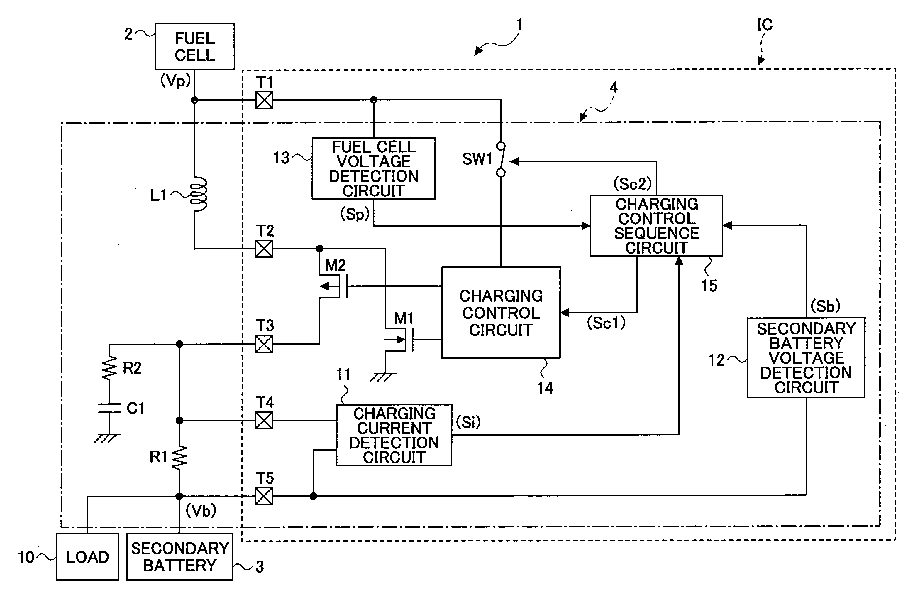
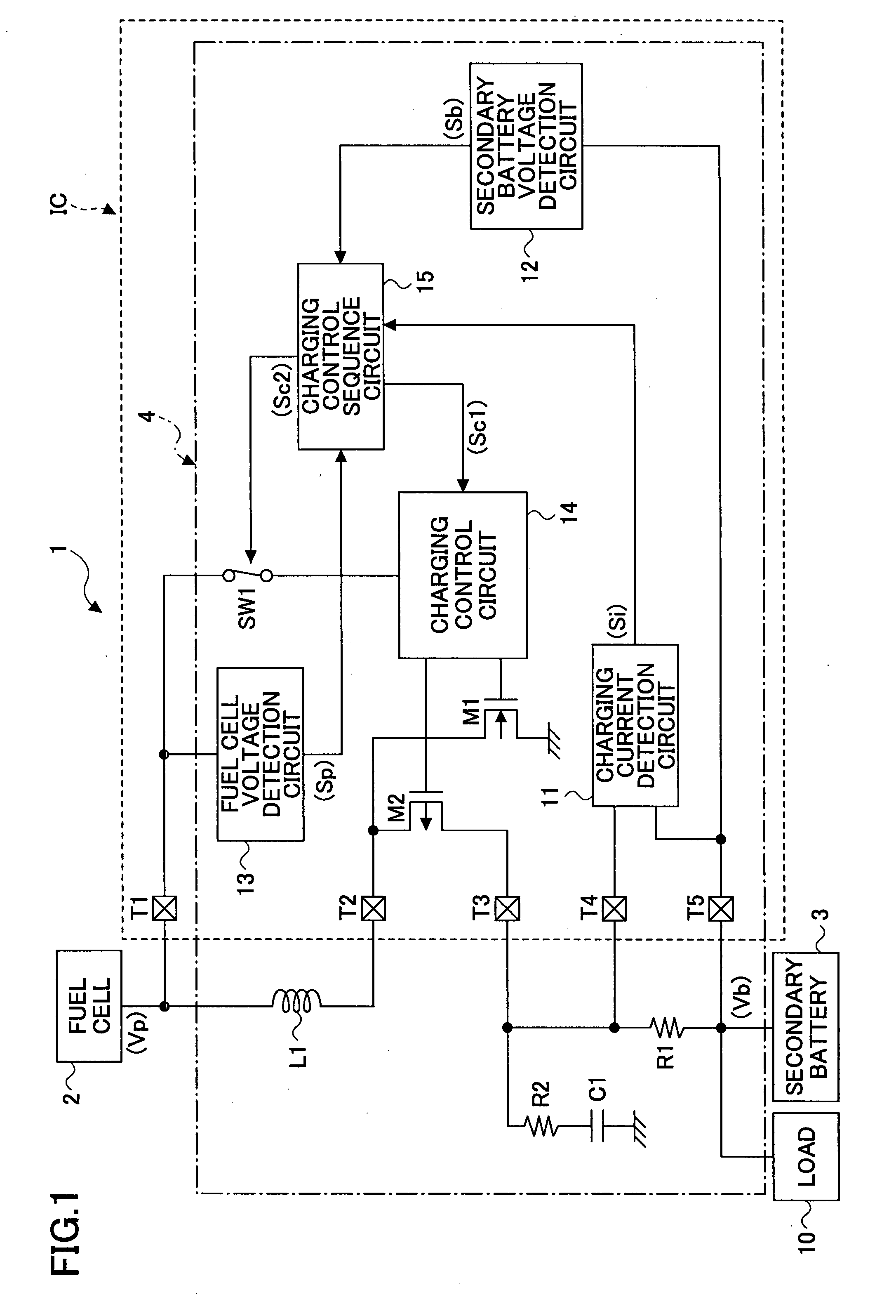
[0047]FIG. 1 is a block diagram showing a configuration example of a power supply unit having a charging circuit according to a first embodiment of the present invention.

[0048] In FIG. 1, a power supply unit 1 includes a fuel cell 2 which outputs a generated voltage Vp, a secondary battery 3 composed of a lithium-ion battery, a charging circuit 4 which charges the secondary battery 3 with the voltage obtained by boosting the fuel cell voltage Vp as a battery voltage of the fuel cell 2.

[0049] The charging circuit 4 includes a switching element M1 composed of an NMOS transistor which performs a switching operation for controlling the output of the fuel cell voltage Vp, a switching element M2 for synchronous rectification composed of a PMOS transistor, an inductor L1, a capacitor C1, resistances R1 and R2, and a first switch SW1. Further, the charging circuit 4 includes: a charging current detection circuit 11 which detects the charging current to the secondary battery 3 from the bot...

second embodiment

[0070] The above-described first embodiment may be arranged so that power is supplied to the charging current detection circuit 11 through the second switch SW2, and when the fuel cell voltage Vp has dropped to less than the specified voltage value Va, the first switch SW1 and the second switch SW2 are each turned off to cut off electrical connections and the power supply to the charging current detection circuit 11 and the charging control circuit 14 is interrupted. Here, those arranged in the above manner will be described as a second embodiment according to the present invention.

[0071]FIG. 4 is a block diagram showing a configuration example of a power supply unit having a charging circuit according to the second embodiment of the present invention. In FIG. 4, components the same as or similar to those of FIG. 1 will be indicated by the same numerals and will not be described below. Here, only parts different from FIG. 1 will be described.

[0072]FIG. 4 is different from FIG. 1 i...

third embodiment

[0085] In the above-described second embodiment, when the fuel cell voltage Vp has become less than the specified voltage value Va, the power supply to the charging current detection circuit 11 and the charging control circuit 14 is interrupted. Alternatively, as a third embodiment of the present invention, there may be provided a temperature sensing circuit which senses the temperature of the fuel cell 2 to interrupt the power supply to each of the charging current detection circuit 11 and the charging control circuit 14 when the temperature of the fuel cell 2 has become greater than or equal to a predetermined value.

[0086]FIG. 6 is a block diagram showing a configuration example of a power supply unit having a charging circuit according to the third embodiment of the present invention. In FIG. 6, components the same as or similar to those of FIG. 1 are indicated by the same numerals and will not be described below. Here, only parts different from FIG. 1 will be described.

[0087]F...


PUM


Abstract

A charging current for a secondary battery is reduced when the secondary battery voltage gets close to a previously set constant voltage. When the charging current has become less than a charging completion current value as a reference for determining whether the charging has been completed, a charging control sequence circuit determines that the charging of the secondary battery has been completed and proceeds to a first flow consumption current mode. The charging control sequence circuit turns off a first switch to cut off an electrical connection to stop the operation of the charging control circuit, whereby a switching element and a switching element for synchronous rectification are turned off to cut-off electrical connections so that the charging current becomes 0 mA.

Description

BACKGROUND OF THE INVENTION [0001] 1. Field of the Invention [0002] The present invention relates to charging circuits of secondary batteries for use in small mobile electronic devices such as mobile phones and notebook computers, a method of controlling the operation of the charging circuits, and power supply units and, in particular, to a charging circuit of a secondary battery which charges the secondary battery using an energy-limited fuel cell as a power supply, a method of controlling the operation of the charging circuit, and a power supply unit. [0003] 2. Description of the Related Art [0004] Recently, there has been a growing interest in the global environment and energy, and in such a circumstance, fuel cells having a low environmental impact have been adopted as a power supply for mobile devices. With mobile phones in particular, it can easily be predicted that, as a result of the introduction of digital terrestrial broadcasting and next-generation communication standards...

Claims


Application Information

Patent Timeline
IPC IPC(8): H02J7/32
CPCH02J7/0068H02J7/0086Y02E70/40H02J2007/0095Y02B40/90H02J2001/004H02J2300/30H02J2207/10H02J7/007182Y02E60/50H01M8/04Y02B40/00Y02E60/10Y02E60/13
Inventor NODA, IPPEI
Owner RICOH ELECTRONIC DEVICES CO LTD
Why Eureka
Try Eureka