
Method and system for fast calibration of three-dimensional (3D) sensors

Active Publication Date: 2008-01-10
MICROSOFT TECH LICENSING LLC
View PDF3 Cites 48 Cited by
  • Summary
  • Abstract
  • Description
  • Claims
  • Application Information

AI Technical Summary

Benefits of technology

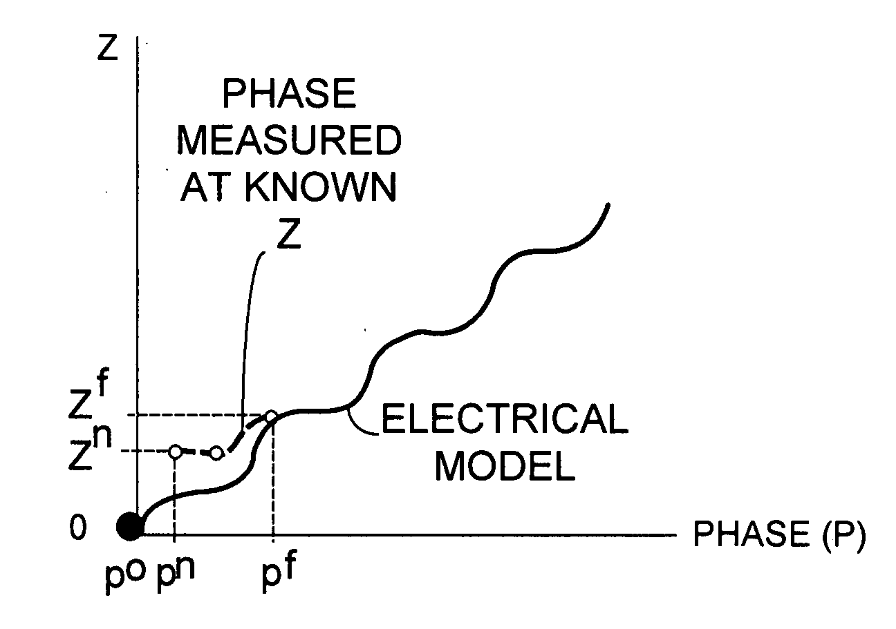
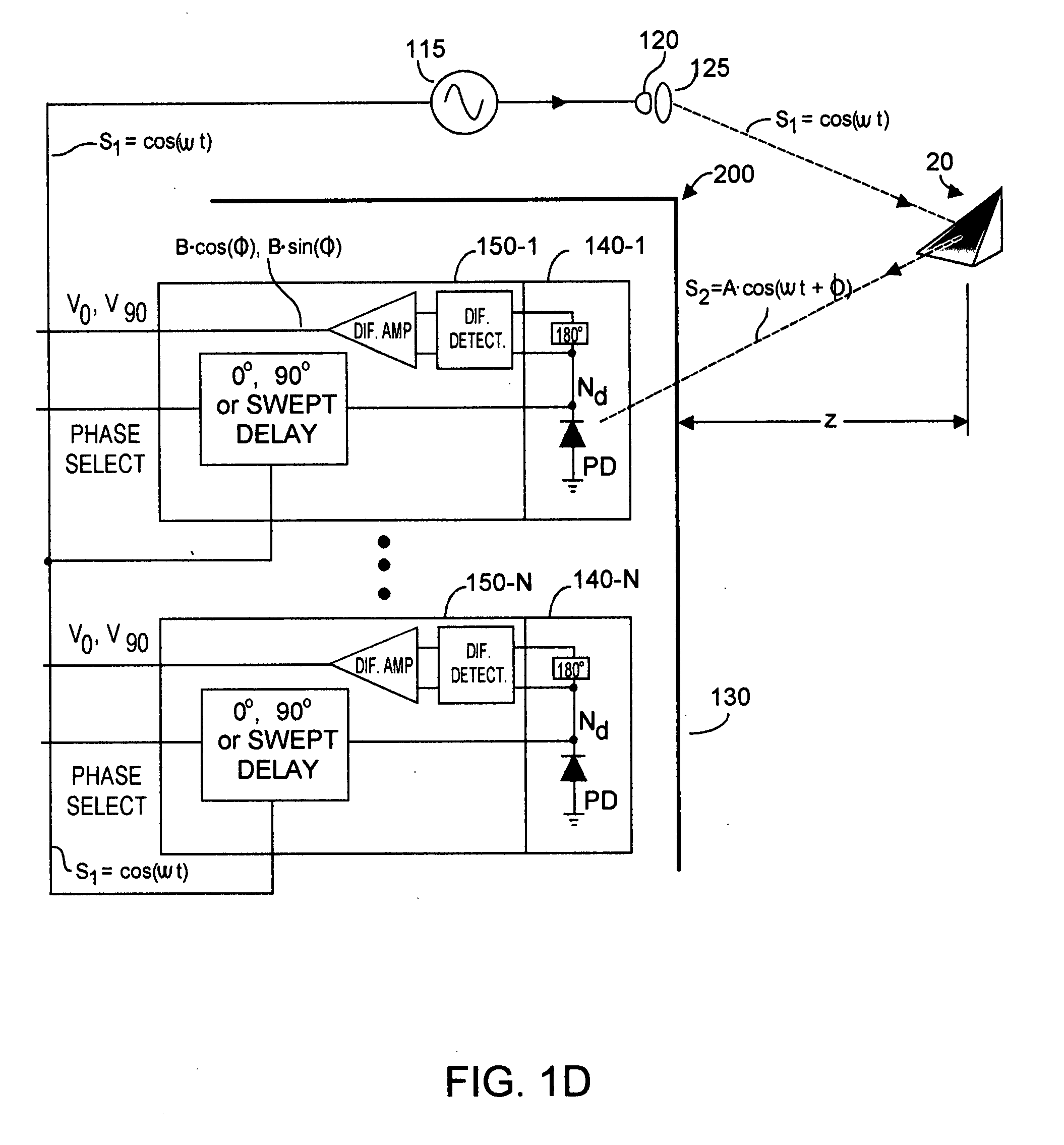
[0019]Rather than acquire calibration data for a TOF system by relocating a target object over a large physical space, embodiments of the present invention calibrate by introducing electrical phase offset into a TOF system to emulate relocation of a stationary target object. As the introduced phase shift is swept in phase, detection samples are acquired from the TOF system. This process takes a relatively short time, and does not require mechanical repositioning of the target object, or of the detector sensor array relative to the target object.
[0021]Model accuracy is enhanced preferably by taking into account electrical and physical characteristics of the TOF system under calibration. More specifically, an electrical model represents distance-vs-phase characteristics of the TOF system that are substantially independent of physical geometry. An elliptical model takes into account geometrical characteristics that are substantially independent of electrical characteristics. The elliptical model advantageously reduces so-called elliptical error that becomes increasing important for small distances Z, where differences in path length from TOF light source to target object, and TOF sensor array to target object are not negligible.

Problems solved by technology

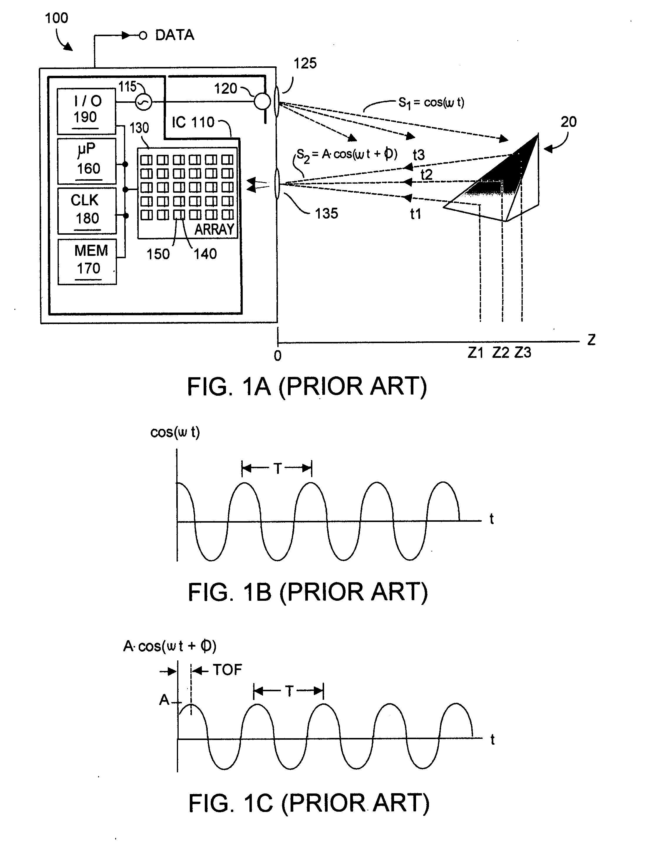
For example, temperature changes in sensor array 130 can increase so-called dark current in pixels 140, which dark current can in turn change measured phase φ. Ambient light can interfere with system-emitted light from source 120, and can result in phase errors.
There is also interpolation error that can only be reduced by increasing the size of the table.
Taking a subset of the operating range and subsequent interpolation results in errors that can be several cm in magnitude.
Another problem from a practical standpoint is the large physical space needed to capture data from the sensor for large field of view (FOV) and operating ranges as the target object is repositioned.
But such prior art calibration procedure has high costs and is not very suitable for calibrating a high-volume product.

Method used


Image

  • Method and system for fast calibration of three-dimensional (3D) sensors
  • Method and system for fast calibration of three-dimensional (3D) sensors
  • Method and system for fast calibration of three-dimensional (3D) sensors

Examples


Embodiment Construction

[0051]In brief, prior art “by example” calibration techniques require repositioning a target object relative to a TOF system and recording data. During run-time of the TOF system, the recorded data is interpolated to provide calibration between phase and distance. By contrast, the present invention calibrates using a stationary target object and electrically introduces phase shift into the TOF system to emulate relocation of the target object. The relatively few data samples thus taken are used to build a model that preferably is a parameterized mathematical representation of the general form x+sin(x). The phase-vs-distance model data is stored as a look-up table that is evaluated (rather than interpolated) during actual run-time operation of the TOF system. The acquired data may be purged once the model data has been stored. Advantageously calibration according to the present invention takes less time to perform, perhaps minutes contrasted with tens of minutes using prior art “by e...


PUM


Abstract

Rapid calibration of a TOF system uses a stationary target object and electrically introduces phase shift into the TOF system to emulate target object relocation. Relatively few parameters suffice to model a parameterized mathematical representation of the transfer function between measured phase and Z distance. The phase-vs-distance model is directly evaluated during actual run-time operation of the TOF system. Preferably modeling includes two components: electrical modeling of phase-vs-distance characteristics that depend upon electrical rather than geometric characteristics of the sensing system, and elliptical modeling that phase-vs-distance characteristics that depending upon geometric rather than electrical characteristics of the sensing system.

Description

RELATION TO PENDING APPLICATION[0001]Priority is claimed to co-pending U.S. provisional patent application Ser. No. 60 / 818,819 filed 6 Jul. 2006, entitled Method and System for Fast Calibration of Three-Dimensional (3D) Sensors.BACKGROUND OF THE INVENTION[0002]Three-dimensional (3D) cameras (or sensors) based on time-of-flight (TOF) principle acquire distance information from object(s) in a scene being imaged. Distance information is produced independently at each pixel of the camera's sensor. Exemplary such systems are described in U.S. Pat. No. 6,323,942 “CMOS-Compatible Three-Dimensional Image Sensor IC” (2001), and U.S. Pat. No. 6,515,740 “Methods for CMOS-Compatible Three-Dimensional Image Sensing Using Quantum Efficiency Modulation” 2003, which patents are assigned to Canesta, Inc., presently of Sunnyvale, Calif.[0003]As described in U.S. Pat. No. 6,323,942, a TOF system emits optical energy and determines how long it takes until at least some of that energy reflected by a tar...

Claims


Application Information

Patent Timeline
IPC IPC(8): G01C3/08G01S7/497G01S17/894
CPCG01C3/08G01C25/00G01S17/89G01S17/36G01S7/497G01S17/894
Inventor BAMJI, CYRUSYALCIN, HAKAN
Owner MICROSOFT TECH LICENSING LLC
Learn More