Connector

a technology of connecting rods and connectors, applied in the direction of coupling device connections, securing/insulating coupling contact members, electrical devices, etc., can solve problems such as affecting connection reliability, and achieve the effects of reducing the projection improving rigidity, and reducing the distance between the outer and inner projections

Inactive Publication Date: 2008-01-10
SUMITOMO WIRING SYST LTD
View PDF4 Cites 8 Cited by
  • Summary
  • Abstract
  • Description
  • Claims
  • Application Information

AI Technical Summary

Benefits of technology

[0008]Outer projections are provided on the outer peripheral surface of the surrounding wall and project towards the inner peripheral surface of the receptacle to substantially fill a clearance between the outer peripheral surface of the surrounding wall and the inner peripheral surface of the receptacle. Inner projections are provided on the inner circumferential surface of the surrounding wall and project towards the outer circumferential surface of the tower to substantially fill a clearance between the inner peripheral surface of the surrounding wall and the outer circumferential surface of the tower. The projections prevent the front holder and the tower from shaking in the receptacle. Additionally, the projections project from both the outer and inner peripheral surfaces of the surrounding wall of the front holder. Thus, projecting distances of the outer and inner projections are reduced and the strengths of the outer and inner projections are greater than shake preventing projections that project from only one of the receptacle and the tower.
[0009]The outer projections and the inner projections preferably are aligned respectively with one another with the surrounding wall therebetween. Thus, rigidity is improved in parts of the surrounding wall where the outer and inner projections are arranged to prevent deformation of these parts of the surrounding wall when subjected to an external force.
[0010]The contact position of mating terminal fittings could displace and impair connection reliability if the tower and the receptacle shake relative to one another. Accordingly, the outer projections or the inner projections preferably are arranged at substantially the same position as the contact position of the terminal fittings with respect to the width direction. Thus, loose movements of the tower in the receptacle are suppressed at a position close to the contact position of the both terminal fittings. Therefore, the connection reliability of the terminal fittings is maintained.

Problems solved by technology

The contact position of mating terminal fittings could displace and impair connection reliability if the tower and the receptacle shake relative to one another.

Method used


Image

  • Connector
  • Connector
  • Connector

Examples


Embodiment Construction

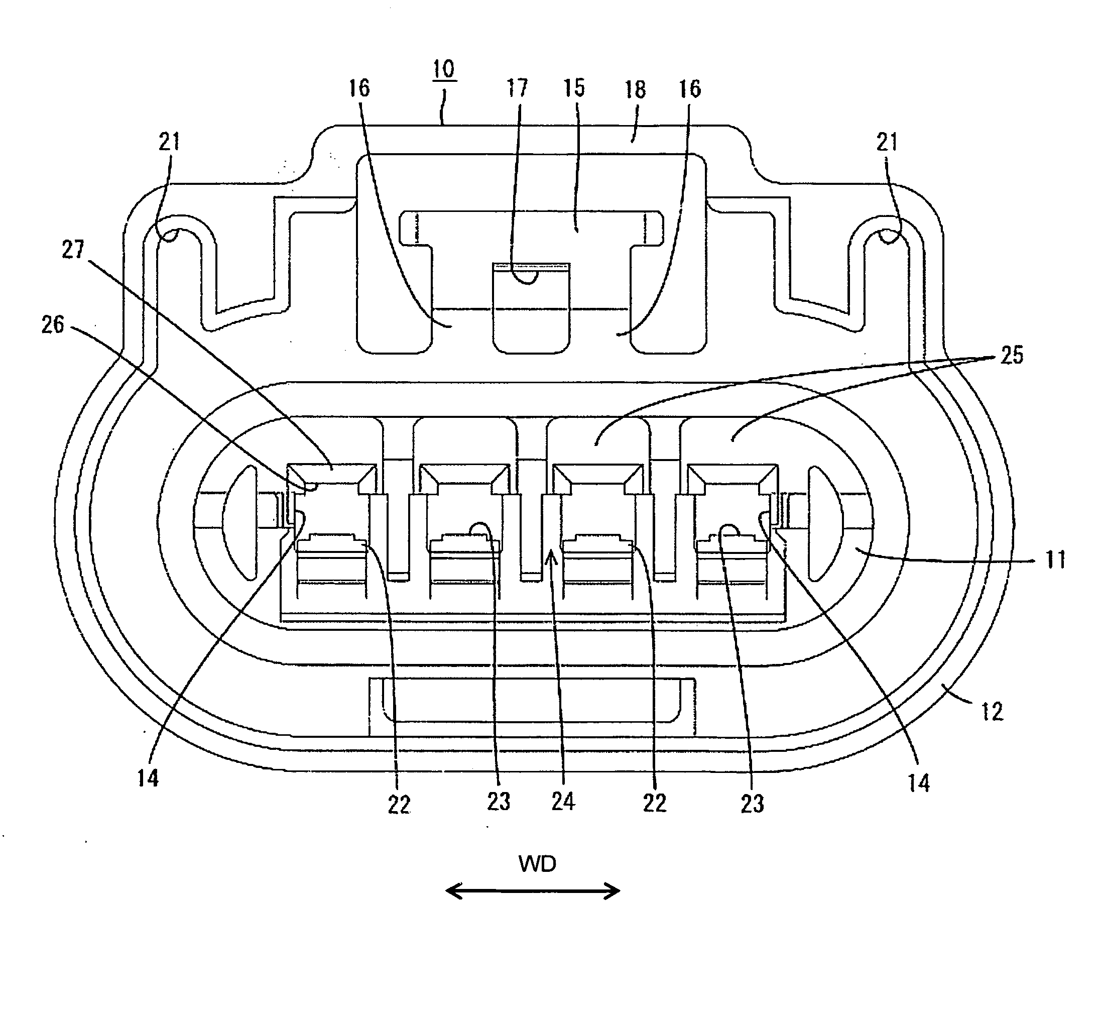
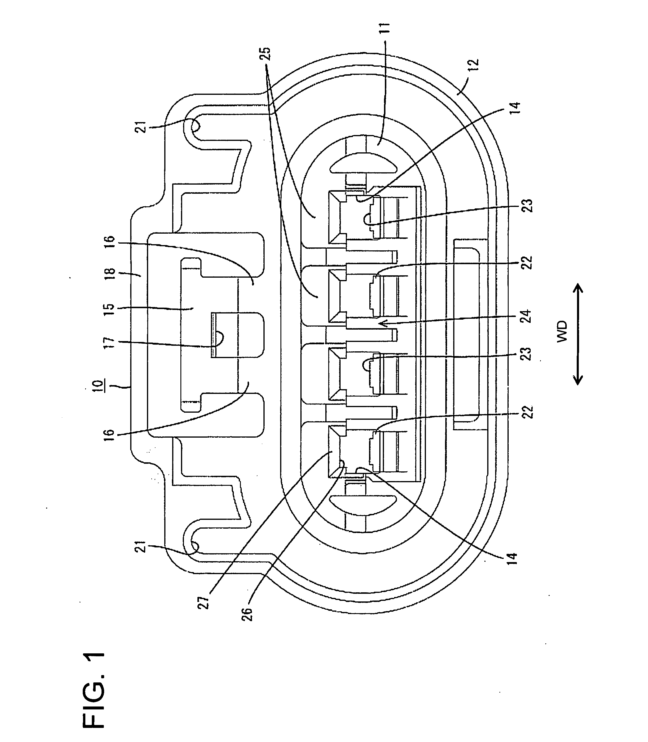
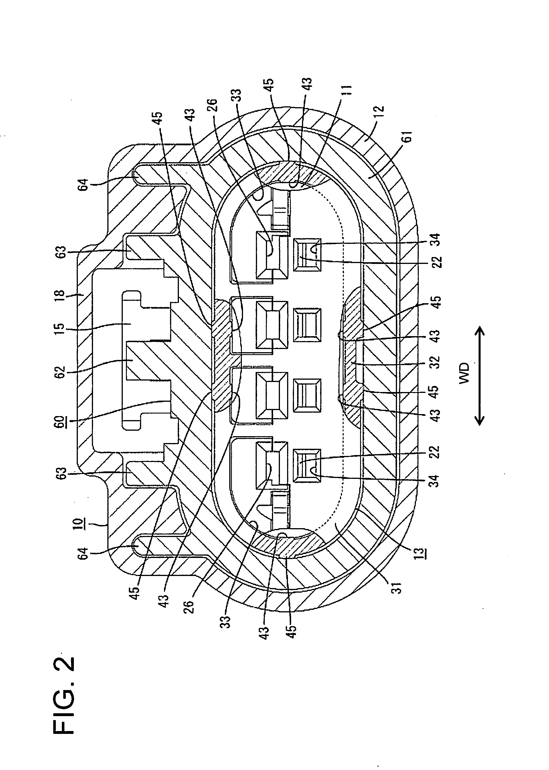
[0022]A connector in accordance with the invention is described with reference to FIGS. 1 to 6. The connector of this embodiment is a fluid- or watertight connector with female and male housings 10, 60 that are connectable with each other. In the following description, ends of the housings 10, 60 to be connected are referred to as the front ends concerning forward and backward directions FBD, and reference is made to FIG. 1 concerning vertical direction.

[0023]The male housing 60 is made e.g. of a synthetic resin and, although not shown in detail, includes a substantially tubular receptacle 61, as shown in FIG. 2, in which male tabs (not shown) project. A lock 62 projects in a widthwise intermediate position of the upper wall of the receptacle 61 and protection walls 63 project from the upper wall of the receptacle 61 at the opposite sides of the lock 62. Guide ribs 64 stand near the outer sides of the protection walls 63.

[0024]The female housing 10 is made e.g. of a synthetic resin ...


PUM


Abstract

A male housing (60) includes a receptacle (61) in which male tabs project. A female housing (10) includes a tower (11) with cavities (14) for accommodating terminal fittings. A front holder (13) is mountable on the tower (11) and has a front wall (31). A surrounding wall (32) projects from a peripheral edge of the front wall (31) for covering the outer peripheral surface of the tower (11). A receptacle (61) is fit on the tower (11) with the front holder (13) thereon. Inner projections (43) are provided on the inner peripheral surface of the surrounding wall (32) and project towards the outer peripheral surface of the tower (11) and outer projections (45) are provided on the outer peripheral surface of the surrounding wall (32) and project towards the inner peripheral surface of the receptacle (61).

Description

BACKGROUND OF THE INVENTION[0001]1. Field of the Invention[0002]The invention relates to a connector.[0003]2. Description of the Related Art[0004]Japanese Unexamined Patent Publication No. 2001-307819 discloses a connector with two housings that are connectable with each other. One housing has a tubular receptacle and the other has a tower with cavities for accommodating terminal fittings. Ribs are provided on the inner peripheral surface of the receptacle and project towards the outer surface of the tower to prevent the tower from shaking in the receptacle. Japanese Unexamined Patent Publication No. 2003-229195 discloses another connector with a cap-shaped front holder mounted on the tower. A front wall of the holder forms front walls of the cavities.[0005]FIG. 7 herein shows a connector with a front holder 1 that can be fit on a tower 2, and then fit in a receptacle 3. A clearance is defined between the inner peripheral surface of the receptacle 3 and the outer peripheral surface ...

Claims


Application Information

Patent Timeline
Patent Type & Authority Applications(United States)
IPC IPC(8): H01R13/40
CPCH01R13/4362H01R9/031
Inventor HIRAMATSU, HIROYUKI
Owner SUMITOMO WIRING SYST LTD
Why Eureka
Try Eureka