Radiation therapy apparatus with selective shielding capability

Active Publication Date: 2008-01-10
XOFT INC
View PDF28 Cites 47 Cited by
  • Summary
  • Abstract
  • Description
  • Claims
  • Application Information

AI Technical Summary

Problems solved by technology

All too often, however, this condition cannot be produced.
Sometimes the cavity cannot be reshaped such that the radiation intensity outside the balloon is insufficiently uniform.
In other instances, nearby tissue structures may lie within the therapeutic range of the radiation outside the balloon, and so would be injured were a therapeutic dose of radiation delivered.
In these instances, the therapist cannot deliver a preferred treatment unless measures are taken to avoid over-treatment of at-risk tissue.
Within practical time constraints, these parameters for a given radioisotope are fixed and they cannot be altered thus offering no possibilities for control.
In addition, is

Method used


Image

  • Radiation therapy apparatus with selective shielding capability
  • Radiation therapy apparatus with selective shielding capability
  • Radiation therapy apparatus with selective shielding capability

Examples


Embodiment Construction

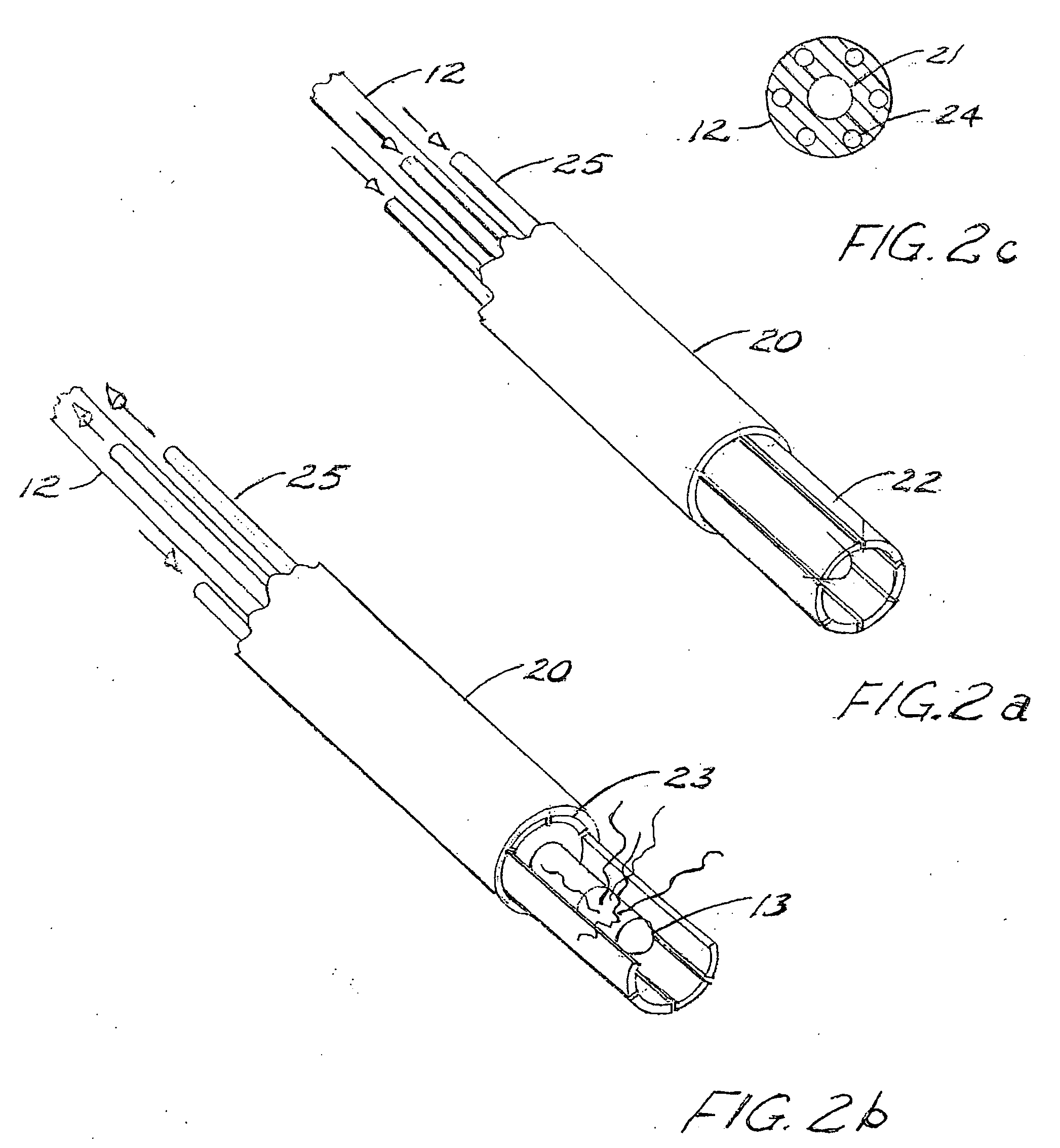
[0050]The figures generally illustrate the shielding embodiments of the present invention wherein the shielding serves to selectively protect certain tissue structures while not interfering with prescribed radiation therapy. In the drawings, the straight sheath or shaft of the applicators illustrated are shown shorter than they would in fact be. Furthermore, balloons are depicted as being transparent in order to more clearly illustrate apparatus within the balloons.

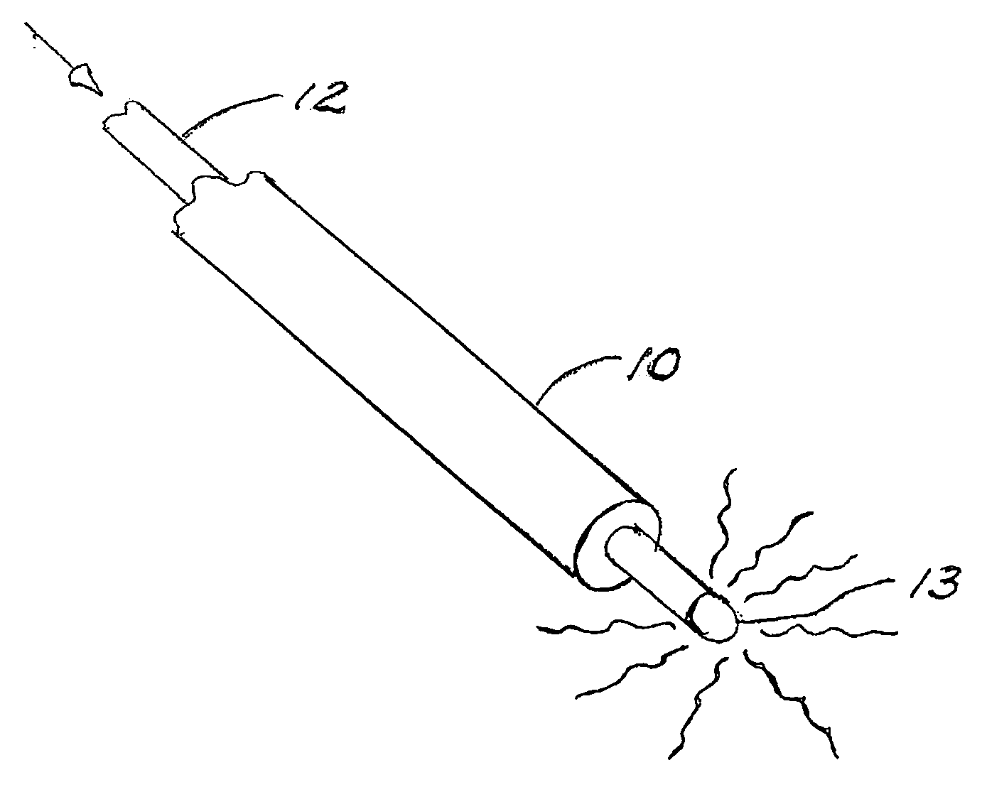
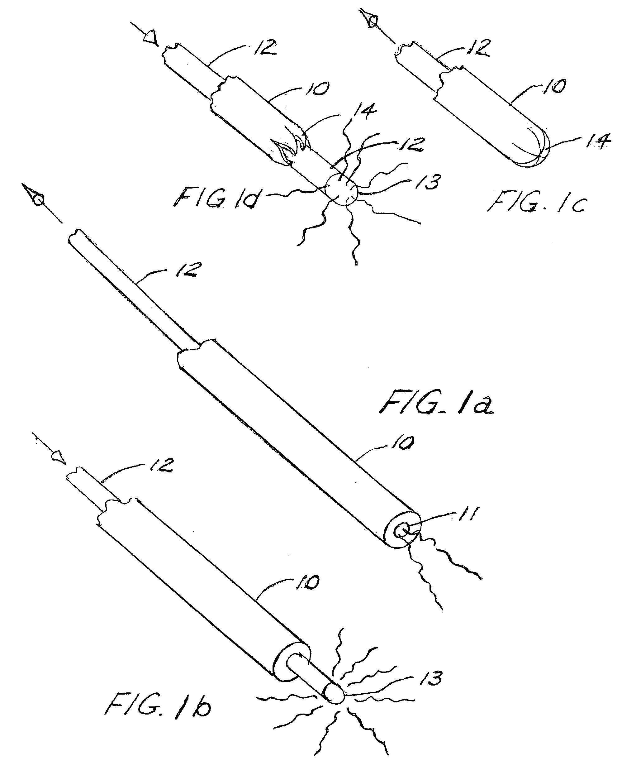
[0051]FIG. 1a shows a simple, solid, tubular attenuating applicator 10 having an open end 11, into the lumen of which is inserted a source catheter 12. Depending on the source and catheter characteristics, radiation can be emitted from the distal end. The degree of collimation will depend on the depth of the source within the applicator lumen. Such an applicator can be fashioned from a polymer like polyurethane, polypropylene, or a metal like stainless steel. In general, at least with electronic radiation sources, most me...


PUM


Abstract

Brachytherapy applicators incorporate various forms of selective shielding devices for controlling the direction and intensity of radiation directed at a patient's tissue. In some forms the applicators include a retractable sheath, in some a series of retractable fingers. In other forms the applicator, having an inflatable balloon, has a shield which is retractable from a position adjacent to the balloon or retracted from the balloon, or a shield can itself be inflatable, separately or together with the balloon.

Description

BACKGROUND OF THE INVENTION[0001]The invention concerns shielding for radiation therapy source applicators, especially adjustable shielding for dynamic control of a radiation emission pattern.[0002]Several forms of ionizing radiation therapy, particularly brachytherapy in which radiation is administered from a radiation source positioned within an anatomical cavity, are delivered using an applicator. Purposes for use of an applicator may include positioning the source within the cavity, mitigating radiation intensity incident on the cavity wall (radiation intensity decays exponentially with distance from the source), or tailoring cavity shape to facilitate radiation delivery in accordance with prescribed therapy parameters. Other purposes may also exist. The anatomical cavity may be a natural cavity, or may result from surgical intervention, for example as in the case of removal of a cancerous lesion.[0003]Some applicators are essentially solid and of fixed configuration in that the...

Claims


Application Information

Patent Timeline
IPC IPC(8): A61N5/00
CPCA61B2017/22051A61B2019/4081A61N2005/1094A61N2005/1003A61N2005/1005A61N5/1015A61B2090/0481A61N5/00A61N5/01A61N5/10
Inventor SMITH, PETER C.KLEIN, MICHAELHAUSEN, HEIKELOVOI, PAUL A.
Owner XOFT INC
Why Eureka
Try Eureka